This is a £3000 system or thereabouts. I doubt the Dali Rubycon 2 speakers were the biggest culprit although I have not auditioned them before. What I heard is more likely electronics. A muddy, bloated bass, a sort of detached and flaccid midrange, lack of consistent PRT. Not very musical. I was listening to tracks that I am very familiar with (Fleetwood Mac and Coldplay) via an iPad controller. The listening room and setup looked competent.
Of course this is only my impression.
I was just really surprised. I expected better at this price.
I heard something similar from my (3 different type of) CLONE Naim. The reason I switched to NCC200. I do not say Naim is a bad amplifier just not my taste. One thing I have to mention to be fair I never tried with Tantalum capacitors. 🙂🙂
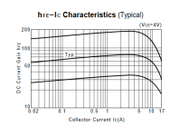
MEGA328P microcontrollerWhat Ic was the transistor measured with?
I still have a myriad Z140 to finish and I will finally be able to attack my new naim clone.
to do so, I will open my first clone that works really well but is closer to a NAP 110, and I will give the references of the parts I used.
Yesterday, I went to an old gentleman who gave me a huge stock of 70s / 80s transistor and military tubes, I was very emotional.
to do so, I will open my first clone that works really well but is closer to a NAP 110, and I will give the references of the parts I used.
Yesterday, I went to an old gentleman who gave me a huge stock of 70s / 80s transistor and military tubes, I was very emotional.
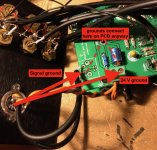
I have just finished the preamp (based on NAC 42, to be connected to the NAP 200 clone via 4 pin DIN cable). One thing which I’m not sure about: The output signal from the preamp and the 24V supply (from the NAP 200 clone) share the same ground pin on the connector. On the preamp PCB the signal ground and the 24V ground are connected. I have now run ground wires from the 4 pin DIN connector to the 24V connectors on the PCB and to the signal output (-) pads on the PCB. Am I causing a ground loop, because these are connected on the PCB anyway? Should I omit the ground wires to the 24V connectors or is it fine like this?
Attachments
Last edited:
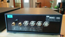
For universal use, Zero zone clones seem to be modified to suit RCA connectors with separate grounded shield leads. Original Naim NAC models use a common ground and common 24VDC power. They have a 4 pin DIN connector for preamp to amplifier connections. Thus only 2 signal leads, power and one ground connection are used with the NAP200 if you included the correct type of DIN connector, 24V power supply and wiring.
Attachments
Am I causing a ground loop, because these are connected on the PCB anyway? Should I omit the ground wires to the 24V connectors or is it fine like this?
From your diagram, they form a triangle. Theoretically, this is a loop. However the wires are short and the currents small so most likely not an issue... You can use only one wire, question is to which point on the pcb. I guess just to the signal ground is ok.
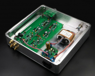
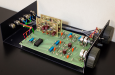
The transformer in the middle picture of Ian's post is interesting. This is a C core with non-overlapping windings between primary and secondary. It also has a copper shield wrapped around it for minimizing high f EMI. Only 4 primary wires: no need for an inter-winding shield. A toroidal transformer is coaxially wound, usually very tightly to reduce leakage, and therefore has a much larger inter-winding capacitance. Some advantages of a toroid are more confined magnetic field, lower leakage flux and smaller physical size for a given power.
These transformers seem to be very popular on eBay recently, and very cheap W/$. Unfortunately, they are junk, or should I say the one that I bought was junk. IMO, not suited for audio at all. It had mechanical hum, large radiation field and the winding voltages are all over the place. I bought it for a tube preamp PS and discarded it imediately.
The mains transformer/rectifier thing is a bit of a disaster really. I imagine in 50 years every car will be electric and young kids will laugh at how we used to drive cars powered by rapid petrol explosions. So I see sucking bursts of energy out of a transformer during a small part of the mains cycle. Pretty crude if you think about it.
My solution is to put the transformers and rectifiers in a separate box. Commercially, this is undesirable if your customers want a single box that's cheaper. As DIYers we don't care so much. 🙂 I am wondering whether to get a piece of thick steel sheet to magnetically shield the psu box from the amp box.
My solution is to put the transformers and rectifiers in a separate box. Commercially, this is undesirable if your customers want a single box that's cheaper. As DIYers we don't care so much. 🙂 I am wondering whether to get a piece of thick steel sheet to magnetically shield the psu box from the amp box.
in steel, it requires a metal thickness of minimum 1.6mm otherwise it saturates the sheet.
the best is the Mumetal to make a good armor
the best is the Mumetal to make a good armor
Member
Joined 2009
Paid Member
... I see sucking bursts of energy out of a transformer during a small part of the mains cycle. Pretty crude if you think about it.
Well it didn't used to be that way. With choke loaded rectifiers the power factor is vastly improved. However, it's more expensive since it requires a choke which is more expensive than bulk capacitors. The modern solution is power-factor-corrected SMPS.
I imagine in 50 years every car will be electric and young kids will laugh at how we used to drive cars powered by rapid petrol explosions.
Super car like McLaren p1 i think, has electric mode for city riding but still rely on gasoline for fast driving. The more explosive the better. The deads will laugh at our kids driving small cars running at 10mph.
Member
Joined 2009
Paid Member
Super car like McLaren p1 i think, has electric mode for city riding but still rely on gasoline for fast driving. The more explosive the better. The deads will laugh at our kids driving small cars running at 10mph.
You must be kidding, electric kills gasoline for performance.
Tesla Roadster 0-60 in <2s
Tesla Roadster (2020 - Wikipedia)
McLarenP1 0-62 in 2.8s
McLaren P1™- Specification
Those little feller transformers are termed "R core" type by the Chinese sellers. They're cheap and thought to be wonderful by some DIY folk but they are just low-cost alternatives to the better iron core types and mostly sold by Ebay or similar on-line marketing platforms. The core is a 2-piece, moulded ferrite form instead of a continuous wound silicon steel strip. The main feature is that they can be quickly assembled by automated winding of the primary and secondaries onto bobbins, slipping them onto each ferrite arm, then clamping the whole assembly with a metal band or frame. That's very useful for making any combination of windings you may need. Problem is; ferrites at 50/60Hz frequency are not ideal and any power transformer above about 20VA will have increasing problems with low flux, leakage and efficiency.
Years ago, C core transformers were popular for DIY too. Unfortunately, they also seemed to combine the worst characteristics of both toroidal and E-I laminated forms. At least that was my experience when the few I used (rated at about 160VA) would vibrate and had a lot of flux leakage. On power-up, amplifier cases would "pop" as the field established itself. The hum and vibration was difficult to eliminate without slackening the core band, realigning the butt joins, packing the bobbins tightly on the core etc. Now that was a PITA and I couldn't accept it then or now for high quality audio. I did come across some imports in later years but most had the same problems to some degree. One notable find was beautifully built though - no problems at all but judging by the assembly quality, it must have cost a small fortune.
Years ago, C core transformers were popular for DIY too. Unfortunately, they also seemed to combine the worst characteristics of both toroidal and E-I laminated forms. At least that was my experience when the few I used (rated at about 160VA) would vibrate and had a lot of flux leakage. On power-up, amplifier cases would "pop" as the field established itself. The hum and vibration was difficult to eliminate without slackening the core band, realigning the butt joins, packing the bobbins tightly on the core etc. Now that was a PITA and I couldn't accept it then or now for high quality audio. I did come across some imports in later years but most had the same problems to some degree. One notable find was beautifully built though - no problems at all but judging by the assembly quality, it must have cost a small fortune.
R core transformer_James transformer-custom toroidal transformer|R core transformer|O core transformer|C core transformer|EI transformer
This is a description of R core. This one “has greater explosive power than toroidal transformer”. 🙂
The core is continuously wound steel ribbon that must be pre tapered in width to create an approximately round cross-section. No air gaps. There is a “gnd” connection that I assume is for the outer copper shield banding.
But how do they get the bobbins on???
Last edited:
Yes, you are right. Even the papers floating about the web say they are wound from tapered silicon steel strip, just not all those fitted in some small box audio products sold on Ebay. I received one that was broken in transit, apparently and that doesn't happen with steel.
I still haven't seen the proper wound core type to see how the approximately circular cross-section fits inside the bobbins or whether if fits closely at all without a lot of packing material. Toroids can be wound with a shuttle, somewhat like that used for weaving but this doesn't look at all simple unless the core or the bobbins are split.
I still haven't seen the proper wound core type to see how the approximately circular cross-section fits inside the bobbins or whether if fits closely at all without a lot of packing material. Toroids can be wound with a shuttle, somewhat like that used for weaving but this doesn't look at all simple unless the core or the bobbins are split.
You must be kidding, electric kills gasoline for performance. Tesla Roadster 0-60 in <2s. McLarenP1 0-62 in 2.8s
Wasn't talking about acceleration. But anyway, there will be time where aeroplanes are all powered by batteries.
Pretty clever whatever it is.I still haven't seen the proper wound core type to see how the approximately circular cross-section fits inside the bobbins or whether if fits closely at all without a lot of packing material. Toroids can be wound with a shuttle, somewhat like that used for weaving but this doesn't look at all simple unless the core or the bobbins are split.
So what do you think? Toroidal with inter-winding shield VS R-core enclosed in mumetal?
- Home
- Amplifiers
- Solid State
- NAP-140 Clone Amp Kit on eBay