Hum should never be heard if the thing is built correctly. I mean, you should be able to press your ear against your woofer and hear absolutely nothing. Unless hum is coming from your source device. Hum can be caused by interference or grounding or instability.
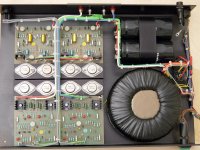
This image of an old NAP250 gives some clues to what Naim does.
You may observe that the transformer has 5 primary leads, two of which will be dual primary windings (series for 230V and paralleled for 115V) and one is a pink wire that connects directly to the mains input socket earth. You can also see the socket earth connected to the chassis nearby. I assume this pink lead connects to an electrostatic shield that combats the inter-winding capacitance.
The transformer outputs have 6 thick wires and two thin, purple wires. There are two secondary, centre-tapped windings and the purples appear to feed the power switch bulb. The centre-taps connect to ground at the smoothing caps. So the transformer secondaries are always tethered to ground which presumably reduces noise because they would otherwise be disconnected most of the time and floating (only connected when the bridge rectifiers are conducting). The direct connection of centre-taps to amp ground couples the transformers inter-winding capacitance between mains and amp ground BUT this problem is reduced by using an electrostatic shield.
No one said power supplies are simple. 🙂
Attachments
Last edited:
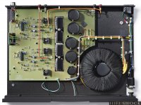
You can see the same transformer wiring in the NAP200.
It is harder to see but again the primary has 5 wires, one of which is a shield connection to the earth connection at the mains socket (probably the green wire). The secondaries are both centre-tapped.
It is harder to see but again the primary has 5 wires, one of which is a shield connection to the earth connection at the mains socket (probably the green wire). The secondaries are both centre-tapped.
Attachments
R114 is 390 ohms.
C1,C2,C3,C6,C7 solid tantalum. C1 & C2 need to be high voltage, like 35V (you can use 47uF for C2 to save cost). Note that both C1 and C2 positive terminals should be on the gnd side (your C1 is shown the wrong way around)
All the pF caps are polystyrene.
R12-15 are the only power resistors. 2.5W wire-wound is enough. Don't use thick film resistors.
You can also use BC550C instead of BC239C if easier. You may need several extras so you can hand select to ideally get the output dc offset below +/-10mV. Maybe buy some sockets to make this easier.
Also, I would be inclined to make C4 47pF to give more stability margin.
I'll mark C1 and C2 as high voltage but I'm not sure why they would need that in normal operation. C1 is that polarity in the "original" nap 250 schematic. Isn't it backwards for half the cycle in either orientation?
Why wire-wound resistors for R12-15? I would think the inductance would be undesirable.
At present, I am just trying to recreate the Nap 250 schematic. I'll send out a modern substitute BOM shortly. I'd also like to assemble a definitive BOM for the 140 -- I've found some but they seem sort of unreliable.
Can anyone point me to the changes between the 250 and 140 schematics? I've seen some mention of changes to the cap values and obviously the bias resistors need to change.
Member
Joined 2009
Paid Member
Why wire-wound resistors for R12-15? I would think the inductance would be undesirable.
why ?
Option A appears to be floating but this is only true for DC. There is inter-winding capacitance in the transformer which effectively connects the mains live to the output windings at AC. This can be mitigated by using a transformer with an electrostatic shield winding that is connected to earth.
Option C tethers the amp gnd to earth through a 10 ohm resistor. I like this as it breaks a potential ground loop and provides some damping. But the 100nF cap shorts the gnd and earth at AC inviting an AC ground loop. Just use a resistor.
Thanks! I’ll try option C without the 100nF cap then. I haven’t got the transformer yet. I ordered a custom one from Tiger in the U.K., I don’t know if it has an electrostatic shield winding – we’ll see …
FIY, is the PCB from the NAP 200 kit that I got today. I made an overlay of front and back.
An externally hosted image should be here but it was not working when we last tested it.
FIY, is the PCB from the NAP 200 kit that I got today.
The parts appear to be good quality, too.

The PCB and the parts list say MPSA18 for TR1, TR2, TR3 and TR3a – but these were missing in the kit.
I have plenty of of BC550C transistors which I intended to use for TR1 and TR2 anyway. What about TR3 and TR3a? Can I use BC550C here as well, as I have so many left? Or should I definitely get some MPSA06 transistors here?

And what is this here, do I need it and which parts do I have to use? ;-)

Tantalums are not like electrolytics and are very prone to damage by reverse bias. The higher the rated voltage the more reverse bias they can tolerate. Look at photos of Naims to check the orientation. There is no official schematic.I'll mark C1 and C2 as high voltage but I'm not sure why they would need that in normal operation. C1 is that polarity in the "original" nap 250 schematic. Isn't it backwards for half the cycle in either orientation?
You can use non-inductively wound but the inductance is pretty small anyhow. I am not certain what type Naim uses but I think they are ordinary Welwyns or equiv.Why wire-wound resistors for R12-15? I would think the inductance would be undesirable.
And what is this here, do I need it and which parts do I have to use? ;-)
That is provision for a power LED and the associated current limiting resistor.
You don't have to use it but I found that with my nap140 clone boards, the power supply caps would remain charged for weeks as there was no discharging element (no LED on those). An LED would take care of that.
(Please be sure to discharge those big caps through a resistor each time before playing with the boards).
Attached is BOM derived from Nap 250 schematic along with the suggested modern replacement parts.
For a power supply, the Nap 250 shows 40VDC rails, the 140 shows 34VDC. I assume that corresponds to approximately 30VRMS and 25VRMS transformers.
I'm still trying to decide if I'm building a 250 or 140.
For a power supply, the Nap 250 shows 40VDC rails, the 140 shows 34VDC. I assume that corresponds to approximately 30VRMS and 25VRMS transformers.
I'm still trying to decide if I'm building a 250 or 140.
Attachments
The Nover brand caps may look nice and shiny but like a lot of Ebay type products, the glossy plastic outer sleeve is the best part of them. Some of these 10,000 uF caps that friends and I had bought as part of kits, were already breaking down when delivered. The aluminium case was often covered in tiny pimples which indicated there were flaws in the metal and/or it was too thin. This does happen with very old caps but on supposed new product, indicates abysmal quality, either in electrolyte, metal or manufacturing process.
Most Nover caps I have seen look sharp but don't perform much better than short life, general purpose grade, no-name caps. With product quality like that in such critical parts of the amplifier, I think you are wasting your time and expectations. Buy decent caps rather than worry about more mundane components and bear in mind that this PCB is nearly a direct copy of the original - only the parts overlay artwork is different so the circuit features on it will be part of the original board design.
As posted earlier, the schematic has been drawn by member Algar_emi, reverse-engineering the board. I've linked it a few times already in this thread, going back to when the Ebay kit was first offered by by Caowei in 2016. The NAP250 schematic is followed generally but there are distinct differences because this is a complete, single board, dual mono amplifier, having the power supplies and 24V preamp supply circuits all on-board. Other kits usually follow the early NAP designs in having only a single channel of the power amplifer per board.
Other notable changes:
The VI limiters are dual-slope type now and are much less intrusive on the audio. They are original in the product and as the lesser evil of having crappy relays in the signal path, it is silly to omit the only protection from abuse like shorted leads, faulty speakers or accidental overdrive that you have. It is popular to remove them, as parroted on many audio forums but consider that your output transistors are now obsolete and probably will be fake or very expensive when as likely, you have to replace them. You can still fit smaller TO3P equivalents but that isn't quite the point of a clone.
The Vbe multiplier transistors are now fitted to the bottom side of the board, reducing the thermal lag of the bias control, which is terrible in most older Naim amplifiers. Take care with orientation of the leads and their length, such that it suits the distance between PCB and the case bottom panel. It needs some clearance, because a case that is built from separate panels but few attachment screws, will flex easily and smash your transistors into the board if too close and you move the amplifier about. That transformer is heavy and it does put a strain on the bottom panel so take care.
Don't omit the 25 x 4 mm heat spreader bar that is located under the power transistors, regardless of what you see in clone assembly pics. Also, the case must be thick - at least 3mm aluminium since the bottom panel is also the heatsink and the joins with the other panels of the case should ideally be continuous and thermally conductive. After all, the amplifier is rated 100W/4R per channel and it won't always be as cool as it seems with just the few watts level most people listen with.
BTW, do not replace ZTX 653/753 with BC parts. The guy who drew up that BOM obviously never listened too hard nor read the part specs.
Last edited:
Nice overlay images.The parts appear to be good quality, too.
An externally hosted image should be here but it was not working when we last tested it.
The PCB and the parts list say MPSA18 for TR1, TR2, TR3 and TR3a – but these were missing in the kit.
I have plenty of of BC550C transistors which I intended to use for TR1 and TR2 anyway. What about TR3 and TR3a? Can I use BC550C here as well, as I have so many left? Or should I definitely get some MPSA06 transistors here?
I would be inclined to use MPSA06 for TR3/3a rather than BC550C.
You could use BC550C for TR3 only.
I agree with Ian Finch (I usually do...which I don't so often do with other members) about the Nover caps. We're talking performance here rather than functionality. Naim goes to a lot of trouble with psus so to keep the faith, as it were, better caps are called for. But if you are on a budget then go with what you've got and upgrade later.
Hey, I’m sitting in a hifi shop right now listening to a Naim Uniti and Dali speakers. It really sounds shite compared to my own system. People pay a lot of money for this stuff. I’m shocked.
Good news for DIYers. You can build a much better system than this. 🙂
Good news for DIYers. You can build a much better system than this. 🙂
Thanks! Again, extremely helpful info and hints from you guys! This really helps a lot. Do these measurements tell anything about the quality or condition of the Nover caps and about the quality of the Sanken transistors?
An externally hosted image should be here but it was not working when we last tested it.
An externally hosted image should be here but it was not working when we last tested it.
So, what's the problem? Is it more like a typical "box store" standard of sound quality, as in no PRT, depth of stereo image etc? Is it more an unfamiliar tone to the sound that you don't like?....now listening to a Naim Uniti and Dali speakers. It really sounds shite compared to my own system.
I imagine that you'd have to compare the Uniti line output signal first, by playing that through your system before drawing conclusions about Uniti's power amplifier or the Dali speakers in combination.
Yes, Ian, I think any system can sound good, and suits our taste better, if tweaked to death. But it requires knowledge/experience and can be costly too (time and unused parts).
Do these measurements tell anything about the quality or condition of the Nover caps and about the quality of the Sanken transistors?
It doesn't tell much about transistor (just that it is normal). But imo the cap quality is just standard, like many industrial caps by Nichicon etc.
This is a £3000 system or thereabouts. I doubt the Dali Rubycon 2 speakers were the biggest culprit although I have not auditioned them before. What I heard is more likely electronics. A muddy, bloated bass, a sort of detached and flaccid midrange, lack of consistent PRT. Not very musical. I was listening to tracks that I am very familiar with (Fleetwood Mac and Coldplay) via an iPad controller. The listening room and setup looked competent.So, what's the problem? Is it more like a typical "box store" standard of sound quality, as in no PRT, depth of stereo image etc? Is it more an unfamiliar tone to the sound that you don't like?
Of course this is only my impression.
I was just really surprised. I expected better at this price.
Last edited:
I like the green glow, Mysteron-esque.Thanks! Again, extremely helpful info and hints from you guys! This really helps a lot. Do these measurements tell anything about the quality or condition of the Nover caps and about the quality of the Sanken transistors?
What johnego said.
No info there about how well the caps are constructed, tho.
What Ic was the transistor measured with?
- Home
- Amplifiers
- Solid State
- NAP-140 Clone Amp Kit on eBay