Sorry one thing. Are these thermal pads usually sticky on both sides. As mentioned when I removed the transistor it was stuck to the pad. If so then I will have to change the pad.
Sorry no need to answer this. I totally forgot about the clamp that attaches to the heatsink, sandwiching the transistor and pad to it. Obviously holding everyhitng in place
Good luck!
Thermal paste is often necessary on demanding applications like CPUs or heavily stressed transistors or ICs. This is because at the microscopic level, the surfaces of the heatsink and component are actually not smooth. The paste fills in the voids to improve thermal contact.
Thermal pads are used when there needs to be an electrical isolation between component and heatsink, as is the case with you amp. Addition of some thermal paste is often done, especially when using hard pads like mica. The softer silicon pads can fill voids by themselves a little better, but sometimes even then thermal paste is used (on both sides of the pad). In this case NAD deemed the addition of thermal paste not necessary, so I would also dispense with it.
Hi there Jitter, thanks for the advice. I have just reinstalled all the new components and... SUCESSS!!!! The amp seems to be working perfectly, all be it the Tone Defeat switch that needs replacing which I am waiting for.
No distortion from the speakers and no magic smoke.
I would just like to say a huge huge thanks for everyone on this forum for all their help and advice. I am pretty much a novice when it comes to these things so the patience everyone has shown has been just fantastic. A NAD C316BEE has been saved from the scrap heap thanks to you all.
I have learnt a lot on this journey and wisdom that I can use going forward if anything like this happens again.
Thanks once gain guys, you ave all been amazing.
For now, case closed.
All the best
Matt
Good to hear!
But before you close the case there's still the simple matter of checking the idle current (and adjusting if necessary).

But before you close the case there's still the simple matter of checking the idle current (and adjusting if necessary).
ah ha thanks for the tip. Ill get onto that. I guess this is becuase they are new parts correct? SO may need fine tuning?
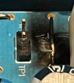
Well that was as fun as a kick in the ****. I managed the blow the Jumper wire next to TP1/2. Now the AMP in down and out. So I now need to replace that.
However, I did take some readings before it went. TP1 - TP2 was reading around 5mV and TP3 - TP4 was reading around 7 so they certainly need some adjusting once I replace the wire.
However, I did take some readings before it went. TP1 - TP2 was reading around 5mV and TP3 - TP4 was reading around 7 so they certainly need some adjusting once I replace the wire.
Attachments
Oh boy, that's not so nice. Please take into account that the wire probably isn't the only part that's damaged.
Yep I was assuming the same thing.
I’ll replace it and then see if it’s still not working and go from there.
Looking at these jumper wires I see that there are different thicknesses. Is there a way of telling what voltage wire I need? I can’t see it from the part number.
I’ll replace it and then see if it’s still not working and go from there.
Looking at these jumper wires I see that there are different thicknesses. Is there a way of telling what voltage wire I need? I can’t see it from the part number.
For now, I wouldn't worry too much about the thickness, you have some fault finding to do. For that you could bridge the gap in the jumper wire with a bit of excess lead from a new resistor soldered on, if its actually burnt through, in the photo it doesn't look like it is, but I can't be sure.
What happened? Did you slip with the meterprobe?
You could already go ahead and measure some parts in the circuit around TP1 like you did the in the beginning of this thread and get an idea of the consequential damage that short caused.
What happened? Did you slip with the meterprobe?
You could already go ahead and measure some parts in the circuit around TP1 like you did the in the beginning of this thread and get an idea of the consequential damage that short caused.
Ye thats correct, one of the probes slipped off the T1 part and onto the jumper. Nice bang and a white spark. So now the amp wont turn on.
I gave the area around the jumper a little clean with a dry ear bud and there is certainly some damage to the jumper. Not sure if its snapped. I will remove it anyway and replace with resistor wire as you suggest.
Ill do as you suggest and take some more readings. Ill let you know how it goes.
Thanks again.
Case NOT closed.
Attachments
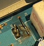
Have now changed the fuse. Also changed the jumper wire to some resistor wire. The original wire hadnt broken all the way through but the mild explosion had eaten into it
But anyhow, so the amp now powers on to standby mode (orange light) from the rear mains switch. To turn it on one needs to press the standby button on the front. When this is pressed, it flicks to the TUNER (blue light) but then back to stand by mode. So thinking has something to do with power supply somewhere.
But anyhow, so the amp now powers on to standby mode (orange light) from the rear mains switch. To turn it on one needs to press the standby button on the front. When this is pressed, it flicks to the TUNER (blue light) but then back to stand by mode. So thinking has something to do with power supply somewhere.
Last edited:
You will need to make measurements, starting with the power supplies. You will need to study the service manual and know how to make the right measurements. This also requires some understanding of the schematics.
At this stage and on this side of the keyboard it has now become hard to think along, especially since you lack basic knowledge. Maybe you know someone who can help you with it?
At this stage and on this side of the keyboard it has now become hard to think along, especially since you lack basic knowledge. Maybe you know someone who can help you with it?

Hi there Jitter.
Just to let you know that I have success. I turned out that I had blown one of the other transitros so on replacement everything worked perfectly. I even managed to adjust the trimpots without blowing it up again. A friend of mine gave me some jumper wire so I could stay steer clear of everything. So all adjusted to 12.5mV and i am now enjoying music through my Q Acoustics 3010i.
Thank so much for all your help and advice and to everyone else on here that helped me on this journey. Its been a very informative process for me and I have gained a lot of insight into how to and how not to do a lot of things.
Ill be sure to be back here if I ever have any other problems as the help has been amazing.
Thanks once again. Case solved.... until next time...
Matt
- Home
- Amplifiers
- Solid State
- NAD C316 BEE Bad channel can it be the relay?