
You already found it to be clean and not affecting the sound, so why replace it?Ive decided to order a new Tone Defeat switch but the original part (SPUN19700) I cant find anywhere. I can find alternatives, 191400 and 191600...
https://tech.alpsalpine.com/e/products/category/switch/sub/03/series/spun/
They are both latching switches, 6 pin but im a little unsure if they would work as i obviously cant find the original spec of the original part so cant compare it?
Any advice here would be superb
Thanks again
There's a place to start. This is likely the result of a fault somwehere else in the circuit.Ok, hold the press. I found something... I believe I have found my problem.
Hi there yes I think I am narrowing the problem down. In the same circuit chain there are two transisistors. I will check both of these. However I am not really sure I am reading the schematics correctly. But on of the transistors sits on the heatsink. Ironically the side that feels cooler when powered up. Not sure if this is anything to go by but I guess its a starting place.
One of the transistors, attacehed to teh Heatsink is an NPN transitor
Oh and the reason why I am changing the switch is on closer inspection after putting it back together I managed to bend one of the copper contacts. Complete rookie mistake and lesson learned.
One of the transistors, attacehed to teh Heatsink is an NPN transitor
Oh and the reason why I am changing the switch is on closer inspection after putting it back together I managed to bend one of the copper contacts. Complete rookie mistake and lesson learned.
Last edited:
It could indeed mean something.
I would start by checking the idling current adjustment as per page 13 of the service manual. You only need a voltmeter to do that.
I would start by checking the idling current adjustment as per page 13 of the service manual. You only need a voltmeter to do that.
HI there, I have taken some readings across some of my transistors, specifically the ones connected to the blown resistor. I have attacehd a pdf of the results. Looking at the schematics it seems that the connecting Transistors are Q115 and Q114 and then looking at my results these two transistors are showing some very unusual activity. I can take these two transistors out and replace them both. but should I also be looking somewhere else for what is causing the unusual readings. Or is it that these just blow sometimes?
Thanks
Thanks
Attachments
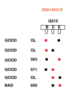
Those values really don't mean that much when measured in-circuit, besides it's R281 that's burnt, so the problem would be more likely with Q214 and/or Q215 than with Q114 and/or Q114.
It would be more useful if you took the schematic and measured the voltages at several points in the circuit around the suspect components. You have a good channel to make comparative measurements against.
It would be more useful if you took the schematic and measured the voltages at several points in the circuit around the suspect components. You have a good channel to make comparative measurements against.
Hi there Jitter. God yes I didnt even think of that. Then i guess it doesnt give me much of a clue then. Thought I was onto something there. But ill do as you suggest and take some more readings. Determined to solve this problem. Thanks for the advice. Ill keep you updated
There's certainly something going on in the circuit behind R281, and is probably the reason why it is burnt. However, I expect there to be more than one thing to be broken and that will affect your readings in-circuit, e.g. the B-E voltage on Q215. On Q115 it reads 57 mV, but as you can see R181 is connected between its B and E pins. Since it's only 51 Ohms, it takes that reading down when compared to the same measurements done on a desoldered component. On Q215 the B-E voltage reads O-L, Over Limit, so that means R281 must be open or gone really high. It seems likely that Q215 has gone short and taken R281 with it. Q214 may or may not be broken too.
You could also power on the amp with nothing connected and volume turned all the way down and take some voltage measurements with respect to circuit ground and write them down like in this post. Do it for both channels, that way you can compare the readings against the good channel. ⚠️ Be careful when working on mains powered equipment. ⚠️
You could also power on the amp with nothing connected and volume turned all the way down and take some voltage measurements with respect to circuit ground and write them down like in this post. Do it for both channels, that way you can compare the readings against the good channel. ⚠️ Be careful when working on mains powered equipment. ⚠️
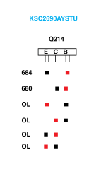
Hi there. Thanks for the info. I did some more thorough measurements of Q215 in circuit. As shown by the image it shows that the E-C reading is wrong which would suggest its gone bad. However. I removed this transistor and measured out of circuit and I got an E-C reading of OL. Which suggests that it isnt broken.
I also removed Q214 and all the readings for that seemed ok as well. So I am not really sure whats going on.
I also removed Q214 and all the readings for that seemed ok as well. So I am not really sure whats going on.
Attachments
Last edited:
I agree that Q215 seems to be broken. Other than that and the fact that R281 has burnt, I cannot draw any conclusions based on these measurements.
It doesn't tell us anything about why it happened which means the actual cause of those components blowing up might still be present.
You could try and replace only those components, but if the cause is still present, they will blow up too.
More measurements are needed, but if you are unsure of how to take them, please get somebody with more experience to help you. If you are unaware of the dangers of working on live mains powered equipment, please have a qualified technician do the repair.
Hi there again. I totally agree. I think I will replace the resistor and transistor. Ill order a few of them so if it does blow then I have replacements.
And yes, if it does blow again then thats something I am not skilled enough to fix so ill certainly be giving it to someone else to do. Thanks so much for all your help. Ill get the parts ordered, put them in and then let you know how it all goes.
Have a great weekend.
And yes, if it does blow again then thats something I am not skilled enough to fix so ill certainly be giving it to someone else to do. Thanks so much for all your help. Ill get the parts ordered, put them in and then let you know how it all goes.
Have a great weekend.
Could I ask you one quick thing about the resistor that I am changing. They obviously come in different PPM ranges. I have read that +100ppm is kind of the industry standard. So I am just looking at this one.
https://www.digikey.se/sv/products/detail/koa-speer-electronics-inc/CF1-4CT52R510J/13537362
has a range from -450/+350 so would this work ok?
https://www.digikey.se/sv/products/detail/koa-speer-electronics-inc/CF1-4CT52R510J/13537362
has a range from -450/+350 so would this work ok?
The bill of materials in the service manual doesn't mention any other properties than value, tolerance and power, so my guess is these will be fine.
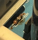
Hi there. I have now received all the new parts so I will be installing them soon. One quick question. it looks like NAD used a thermal pad inbetween the transistor and the Heatsink. (See image.) When I took the transistor off it was stuck to this however I am guessing that over time thats just what happens.
This pad is easily removable and I have bought some Thermal Arctic Cooling MX-4 to use instead. or do you think I should just keep this pad in place? I presume I dont need to bond the transistor to this in any way.
Thanks
This pad is easily removable and I have bought some Thermal Arctic Cooling MX-4 to use instead. or do you think I should just keep this pad in place? I presume I dont need to bond the transistor to this in any way.
Thanks
Attachments
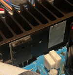
The thermal pad is vital from an insulation point of view. Without it, the collector of the transistor will create a short circuit to the heatsink as it is connected to the metal backside of that transistor. Make sure the pad is in good shape and after mounting measure continuity between the centre pin and the heatsink. There should be none. If there is and you power it on anyway, the magic smoke will escape.
Ah ha ok, I had read that some people use thermal paste instead of the pads so was just wondering if there was any difference. The pad itself is in good condition. Ill probably buy some fresh stuff though jsut to be sure.
Ill make sure to measure the continuity as well. Thanks for the advice. Fingers crossed for no magic smoke. ;I
Ill make sure to measure the continuity as well. Thanks for the advice. Fingers crossed for no magic smoke. ;I
- Home
- Amplifiers
- Solid State
- NAD C316 BEE Bad channel can it be the relay?