ok so thats ok then.i found a diode round the wrong way this morning-i wasnt getting any voltage upstream which is why i suspected this, but it hasnt made any difference other than the watt meter on the front that originaly was straying upwards now isnt moving at all when switched on and i cant get my head round some of the voltages at the moment.just working my way through.
i still have -24v on this faulty channel.the centre on the other one is about 5mv
one i dont get is R605 and R606 (390ohm)
R605 is supposidly the good channel and the voltage drop is around 4v yet
R 606 is about 600mv
ive had both out and both read ok
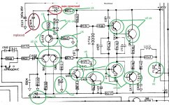
not recorded any voltages yet but diagram attached shows what components have been checked/replaced, the reason is so many components in that location were blackened, so i changed them after testing them as faulty.
i will do your diode test later but given your comment it can wait as i think there would be alot more wrong if that was faulty?
anyway ill carry on🙂
i still have -24v on this faulty channel.the centre on the other one is about 5mv
one i dont get is R605 and R606 (390ohm)
R605 is supposidly the good channel and the voltage drop is around 4v yet
R 606 is about 600mv
ive had both out and both read ok
not recorded any voltages yet but diagram attached shows what components have been checked/replaced, the reason is so many components in that location were blackened, so i changed them after testing them as faulty.
i will do your diode test later but given your comment it can wait as i think there would be alot more wrong if that was faulty?
anyway ill carry on🙂
Attachments
I've just deleted my reply because I see you mentioning the offset as negative in value in post #41 and as '21 volt' in post #36.
Is it positive or negative?
Is it positive or negative?
now the lamp is on,so im not having a good day.
update, now im only getting 16v off the rectifier so im fearing the transformer maybe has gone
update, now im only getting 16v off the rectifier so im fearing the transformer maybe has gone
Last edited:
scrub that it cant be the tranny, im only getting 170v onto the main switch from the lamp tester, is this because its drawing so much current? i have confirmed 240v at the switch if i just plug it in(without turning on) into an independent socket.
it wasnt quite the lightbulb moment i was looking for 😀now the lamp is on,so im not having a good day.
update, now im only getting 16v off the rectifier so im fearing the transformer maybe has gone
def -24v
update since that post ,its now -16v
Right then...
now the lamp is on,so im not having a good day.
update, now im only getting 16v off the rectifier so im fearing the transformer maybe has gone
So that could be diode related. Short the diode package out with a link until the whole amp is corking correctly. Tranny will be fine.
scrub that it cant be the tranny, im only getting 170v onto the main switch from the lamp tester, is this because its drawing so much current? i have confirmed 240v at the switch if i just plug it in(without turning on) into an independent socket.
The bulb is doing its job.
Link those diodes out on both channels and see where it is at.
the 2 package ones on the heatsink
ive had a weird day.some of the transistors were put in wrong and now im wondering if its something ive done so ive taken them all out, checked and double checked they are now right
must be the covid, apparently it can cause foggy vison? and poor memory short term!! not a good combination when doing this stuff 🙁
Maybe 🙂 you just need to carefully check as you go along.
The diode package is marked D604 in your diagram earlier. Those are the ones to link out. They are on the heatsink to track the temperature of the outputs and keep the bias reasonably constant with temperature change.
The diode package is marked D604 in your diagram earlier. Those are the ones to link out. They are on the heatsink to track the temperature of the outputs and keep the bias reasonably constant with temperature change.
so 2 things
1st ive done as you asked and shorted outboth diode sets, once again you are right, i now have 240v back on the switch and the lamp is off. reading on that (L)channel is - 30v(minus)
(R) is 45mv
2nd you cant trust info in the internet.I used a data sheet to get the pin out on an old transistor and it was wrong Q606 B/E reversed so ive put it bacvk in the correct way.
Its quite hard to trace the front board print as it has loads of securing glue all over it oscuring the print and also details on components.ive got rid of most of it now so i can see most detail.
so i guess now i just have to work my way through it checking now.
My first thoughts now would be that there is an issue around Q606 and Q608. Both diode packs won't be faulty so I think you had excess current because to much current is flowing in the diodes and that is raising the bias generator voltage.
So this is the reply I deleted earlier but now changed for a negative offset... but I'm guessing Q606 and/or Q608 have an issue.
When you have a problem like this you need to think in terms of quick tests to locate the area of the fault. First thing is to check all the four supplies. That is the -/+30 volts and the two supplies derived off these which can be picked up on C624 and C626.
If you have -30v on the output then we will work with that and look earlier in the stages to see what is going wrong. There will (should) be a point where a massive error occurs in the area of the fault because this is a feedback type circuit and the loop may well be broken...
So quick checks are.
1/ Output at -30 volts DC
2/ The voltage on R626 (the now shorted diode pack) should be about -31 volts.
3/ The voltage on the base of Q602 (input transistor) should be around zero volts DC.
Now the real fault finding starts
4/ Q604 should be being turned ON because off the high -30 volt offset which enables Q602 to be fully OFF and non conducting in this fault condition.
This means you should see a very low voltage across R608. Less than 0.3 volt at a guess.
If it is low then that shows there is likely a fault around Q606 and Q608.
If it is much higher and is at around 1.5 volts then you need to look carefully around the two input transistors.
If it looks correct and is low then Q606 should be turned off and that should be allowing Q608 to be off and so the collector volts of Q608 should rise toward the positive rail to lower the offset.
So you should find somewhere that the loop is broken with those measurements.
If you get stuck then do a fresh copy of the diagram and write the transistor voltages on, or post the voltages here clearly.
im not sure who ever worked on this before had the same trouble as me, but the transistors i have are not corresponding to one of the data sheets i have
2n6555/2n6552 Q606,608,610,612
data sheet suggests
1 base
2 collector
3 emmiter
not on the ones i have the base is in the middle as i have tested them, and im sure this is why i am getting the wrong end of things as they are fitted accoring to the data sheet,so i am unsighted as tho which is B/E on each one
2N6552
Datasheet, Equivalent, Cross Reference Search. Transistor Catalog
if i fit according to this data sheet the light is on(maybe thats right i dont know)
2N6552 npn transistor complementary pnp, replacement, pinout, pin configuration, substitute, equivalent smd, datasheet
if i fit according to this data sheet the light is off(red herring?)
if i replicate whats on the other channel and fit them exactly the same, the light is off
confused .com
i will of course do what you suggest, and i think i could have found the fault by now possibly but i have absolutly no confidence about the parts im fitting, and i dont have any to put back unless there is an alternative i can use
i have new NPN BD139 and PNP b546-Y
anyway so before i carry onto serious fault finding i have to be sure they are all fittied correctly in my mind
update on above, i think i may have it now.
lamp is off and we are back to where i started realy with that watt mater elevated so i think we can start your testing now.
Last edited:
My first thoughts now would be that there is an issue around Q606 and Q608. Both diode packs won't be faulty so I think you had excess current because to much current is flowing in the diodes and that is raising the bias generator voltage.
So this is the reply I deleted earlier but now changed for a negative offset... but I'm guessing Q606 and/or Q608 have an issue.
When you have a problem like this you need to think in terms of quick tests to locate the area of the fault. First thing is to check all the four supplies. That is the -/+30 volts and the two supplies derived off these which can be picked up on C624 and C626.
If you have -30v on the output then we will work with that and look earlier in the stages to see what is going wrong. There will (should) be a point where a massive error occurs in the area of the fault because this is a feedback type circuit and the loop may well be broken...
So quick checks are.
1/ Output at -30 volts DC
2/ The voltage on R626 (the now shorted diode pack) should be about -31 volts.
3/ The voltage on the base of Q602 (input transistor) should be around zero volts DC.
Now the real fault finding starts
4/ Q604 should be being turned ON because off the high -30 volt offset which enables Q602 to be fully OFF and non conducting in this fault condition.
This means you should see a very low voltage across R608. Less than 0.3 volt at a guess.
If it is low then that shows there is likely a fault around Q606 and Q608.
If it is much higher and is at around 1.5 volts then you need to look carefully around the two input transistors.
If it looks correct and is low then Q606 should be turned off and that should be allowing Q608 to be off and so the collector volts of Q608 should rise toward the positive rail to lower the offset.
So you should find somewhere that the loop is broken with those measurements.
If you get stuck then do a fresh copy of the diagram and write the transistor voltages on, or post the voltages here clearly.
so before i go any further output is now +30v not -30v
Last edited:
1/ Output at -30 volts DC- +31v
2/ The voltage on R626 (the now shorted diode pack) should be about -31 volts. yes -31 volts
3/ The voltage on the base of Q602 (input transistor) should be around zero volts DC. 196mv
Now the real fault finding starts
4/ Q604 should be being turned ON because off the high -30 volt offset which enables Q602 to be fully OFF and non conducting in this fault condition.
This means you should see a very low voltage across R608. Less than 0.3 volt at a guess. 5.5v across in -31/ out-26v
Q608 has -31v emitter -31v base +31v collector
where as Q607 has a few mv across the emitter and -31v on base and collector
Last edited:
There seems to be a lot going on here. If you have doubts over transistor polarities then you need to rig a little test circuit up (battery and LED etc) to try each one and determine the leadout configuration and whether it is NPN or PNP.
Obvious problem from the above measurement is the output at +31 and having -31 on R626. That means 62 volts between output and the diode pack. That would only really be possible with an open circuit condition.
Are you sure it is negative on the diode pack?
R608 with 5.5 volts across it means one both of Q606 and Q608 is open circuit B-E
so shorted diode voltage on good channel 20mv? on bad channel +30v
i could go round in circles all week with this little lot.Is it worth taking every transistor out and verifying its both the correct polarity and it working
i could go round in circles all week with this little lot.Is it worth taking every transistor out and verifying its both the correct polarity and it working
Last edited:
So it is plus 30 and not minus 31 (as you reported in post #55 🙂)
So for a positive offset you do this, and this is what I posted originally yesterday but deleted:
When you have a problem like this you need to think in terms of quick tests to locate the area of the fault. First thing is to check all the four supplies. That is the -/+30 volts and the two supplies derived off these which can be picked up on C624 and C626.
If you have +30v on the output then we will work with that and look earlier in the stages to see what is going wrong. There will (should) be a point where a massive error occurs in the area of the fault because this is a feedback type circuit and the loop may well be broken...
So quick checks are.
1/ Output at +30 volts DC
2/ The voltage on R626 should be about +31 volts.
3/ The voltage on the base of Q602 (input transistor) should be around zero volts DC.
Now the real fault finding starts
4/ Q604 should be being turned OFF because off the high 30 volt offset which enables Q602 to be fully on and conducting in this fault condition.
This means you should see about 1.5 volts across R608.
If it is a lot higher than that then there is a fault around Q606 and Q608.
If it is much lower than 1.5 volts then you need to look carefully around the two input transistors.
If it looks correct at around +1.5v then Q608 should be turned on and that should be pulling the voltage on the collector of Q608 toward the negative rail to lower the offset.
So you should find somewhere that the loop is broken with those measurements.
If you get stuck then do a fresh copy of the diagram and write the transistor voltages on, or post the voltages here clearly.
You shouldn't need to go that far tbh but if you have doubts then yes, take one out and check it for polarity and functionality.
Even if there are a few such issues the correct interpretation of voltage readings should point them out as a problem because the voltages would be non sensical across the junctions.
So for a positive offset you do this, and this is what I posted originally yesterday but deleted:
When you have a problem like this you need to think in terms of quick tests to locate the area of the fault. First thing is to check all the four supplies. That is the -/+30 volts and the two supplies derived off these which can be picked up on C624 and C626.
If you have +30v on the output then we will work with that and look earlier in the stages to see what is going wrong. There will (should) be a point where a massive error occurs in the area of the fault because this is a feedback type circuit and the loop may well be broken...
So quick checks are.
1/ Output at +30 volts DC
2/ The voltage on R626 should be about +31 volts.
3/ The voltage on the base of Q602 (input transistor) should be around zero volts DC.
Now the real fault finding starts
4/ Q604 should be being turned OFF because off the high 30 volt offset which enables Q602 to be fully on and conducting in this fault condition.
This means you should see about 1.5 volts across R608.
If it is a lot higher than that then there is a fault around Q606 and Q608.
If it is much lower than 1.5 volts then you need to look carefully around the two input transistors.
If it looks correct at around +1.5v then Q608 should be turned on and that should be pulling the voltage on the collector of Q608 toward the negative rail to lower the offset.
So you should find somewhere that the loop is broken with those measurements.
If you get stuck then do a fresh copy of the diagram and write the transistor voltages on, or post the voltages here clearly.
i could go round in circles all week with this little lot.Is it worth taking every transistor out and verifying its both the correct polarity and it working
You shouldn't need to go that far tbh but if you have doubts then yes, take one out and check it for polarity and functionality.
Even if there are a few such issues the correct interpretation of voltage readings should point them out as a problem because the voltages would be non sensical across the junctions.
ill have a look now, but dont forget ive taken out transistors and changed orientations so maybe this would have changed it from -31 to +31?
anyway
1/ Output at +30 volts DC - yes +30v
2/ The voltage on R626 should be about +31 volts. -5.060v
3/ The voltage on the base of Q602 (input transistor) should be around zero volts DC. 194mv
so input transistors Q602 and Q 604?
anyway
1/ Output at +30 volts DC - yes +30v
2/ The voltage on R626 should be about +31 volts. -5.060v
3/ The voltage on the base of Q602 (input transistor) should be around zero volts DC. 194mv
so input transistors Q602 and Q 604?
Last edited:
so ive just about had enough for today, been at it since 7am and i havent realy got anywhere.
have started to take some voltages, but im starting to wonder if both channels have issues, any ill concentrate on one at a time
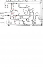
some voltages ive taken so far, not many but my heads gone now, time to stop. not a good weekend 🙁
have started to take some voltages, but im starting to wonder if both channels have issues, any ill concentrate on one at a time
some voltages ive taken so far, not many but my heads gone now, time to stop. not a good weekend 🙁
Attachments
- Home
- Amplifiers
- Solid State
- NAD 3030 in a mess