🙂 OK
For when you are ready there is one standout problem with those readings and that is +8 volts on the base of Q606. Something is open circuit or fitted incorrectly or a wrong polarity part.
Check R616, R618 and R620. If those are OK then either one of both of Q606 and Q608 are at fault.
For when you are ready there is one standout problem with those readings and that is +8 volts on the base of Q606. Something is open circuit or fitted incorrectly or a wrong polarity part.
Check R616, R618 and R620. If those are OK then either one of both of Q606 and Q608 are at fault.
base of Q606? or C606🙂 OK
For when you are ready there is one standout problem with those readings and that is +8 volts on the base of Q606. Something is open circuit or fitted incorrectly or a wrong polarity part.
Check R616, R618 and R620. If those are OK then either one of both of Q606 and Q608 are at fault.
Sorry, scrub what I said... I'm getting confused as well with this. So that 8 volt was on the cap, not the base. My fault.
Let me start again. Thinking aloud.
Why is there -30V on Q602 collector and only -26v on Q604. -26 sounds right so that suggests the -30 is feeding back from the output stage... and there is only one route.
I think you have to begin by checking all those resistors in that area of the circuit, so that's R616, 618, 620 and also check R630 which is in the supply rail. Lets get those out of the way.
If they are all good then I think you have to look at Q606 and Q608 as being a problem.
That negative 26v should put a limit on how negative any voltage in that area to the left of R630 can be. So I'm thinking that -30 is feeding back through either faulty or incorrect Q606 or Q608.
so if im looking at this correctly, the feed back is Q616 VIA Q612 and Q608 onto the base of Q 606?
Sort of, but it is feedback in the sense of being unwanted, maybe leakage is a better term.
I'm wondering if there is more than one problem, particularly as you are unsure of transistor pinouts etc.
There is another way to approach this. Look at the circuit.
We can do a quick and dirty test on the output stage to make sure there is nothing drastic wrong there. It should only take a few minutes.
With the diode pack still linked out remove R624 and Q608.
Connect a 10k or near value from the linked diode pack to ground and switch on.
The output voltage at the speaker should be zero volts and there should be no voltage across the 10k.
If it passes that test then switch off and now connect the 10k resistor to the plus supply.
The output should now be at +30 volts (supply) and there should only be 1 volt or so across the 10k
Now move the resistor to the negative rail and test again. The output should be negative 30 volts and again there should only be a volt or so across the 10k.
If all that is OK then the output stage appears functional. It is allowing the output to follow whatever voltage is applied to the drivers, which is really all the output stage does. That then leaves us with finding out why there is a higher negative voltage (-30) on the stage before this when that stage has only -26 as its supply.
With the diode pack still linked out remove R624 and Q608.-removed
Connect a 10k or near value from the linked diode pack to ground and switch on. connected as suggested
The output voltage at the speaker should be zero volts and there should be no voltage across the 10k.
140mv at speaker terminals
2.5mv across 10kR
looking at the diagram, i presume doing this eliminates any way voltage can reach the neg rail?
Last edited:
That all sounds good so far. 140mv is fine. Its a quick test that shows the outputs and drivers are not leaking supply voltage back to the where the diode pack is.
Now quickly try the 10k to each rail. The speaker output should follow but there should still only be a very low voltage across the 10k.
Now quickly try the 10k to each rail. The speaker output should follow but there should still only be a very low voltage across the 10k.
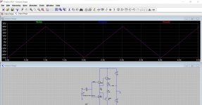
Just so you can follow the logic...
This is similar to your NAD output stage. Whatever voltage is applied to the input side should also appear at the output. The transistors give no voltage gain but they do have massive current gain connected this way as the first transistor feeds into the second transistor in each upper and lower half.
This shows the input voltage, the base voltage and the output voltage. All are similar.
The massive current gain means the stage takes very little current from the voltage source driving it.
Nothing from the supply rails can feed back to the input side.
The input voltage is slowly going from -30 to plus 30 here.
Attachments
connected to +30v rail
+30v at speaker terminals
30mv across 10kR
connected to -30v rail
-30v across speaker terminals
900mv across 10kR
+30v at speaker terminals
30mv across 10kR
connected to -30v rail
-30v across speaker terminals
900mv across 10kR
I'm going to say at this point that that is a little suspect, particularly the 900mv across the 10k.
That level of voltage suggests the current gain of the lower half of the stage (the two PNP's) is low. It just 'feels' wrong to me.
You would get that effect if either of the two PNP's was either faulty or had a missing connection... or if there is doubt, was incorrectly fitted.
It would also do this if either PNP had the supply missing to the collector.
To be absolutely honest, the 30mv reading also looks high and again exactly the same applies to the upper half of the circuit.
It needs investigation.
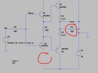
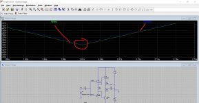
Try the sim I attached. Add a 1k8 load to the output (in place of a speaker... in the sim, not the real amp) and snip the collector of each PNP in turn. The 1k8 is the feedback resistor which is the only load the output stage is driving. Look at the voltage across the 10k at the -30v point. Its about 900mv.
This is the detail we have to get into now to fix this. I suspect you have more than one fault/error causing the overall fault.
That level of voltage suggests the current gain of the lower half of the stage (the two PNP's) is low. It just 'feels' wrong to me.
You would get that effect if either of the two PNP's was either faulty or had a missing connection... or if there is doubt, was incorrectly fitted.
It would also do this if either PNP had the supply missing to the collector.
To be absolutely honest, the 30mv reading also looks high and again exactly the same applies to the upper half of the circuit.
It needs investigation.
Try the sim I attached. Add a 1k8 load to the output (in place of a speaker... in the sim, not the real amp) and snip the collector of each PNP in turn. The 1k8 is the feedback resistor which is the only load the output stage is driving. Look at the voltage across the 10k at the -30v point. Its about 900mv.
This is the detail we have to get into now to fix this. I suspect you have more than one fault/error causing the overall fault.
Attachments
No, I would leave it so you can retest with the 10k. We have to figure out why you are seeing that volt drop across the 10k... well the reason is the stage is loading it to heavily because the current gain seems low. We need to find a reason why.
Have to go for now
(The 1k8 is whatever value R614 is in your amp. That is the load the stage is driving)
Have to go for now
(The 1k8 is whatever value R614 is in your amp. That is the load the stage is driving)
so some real good progress
i thought i would do some checks again on the transistors as i wasnt realy happy with them all
i removed Q606 and the collector leg fell off so it can only just have been on there.
also i did a bit of reserch on the amp and there isnt alot out there in terms of reference material but i did find a frech site with some reasonable pictures that i could use as a comparison for transistor orientation and Q608 was insrted wrongly, so this was replaced correctly.
so i replaced the broken transistor (C1571) with a BD 139 for now and it works(is this ok??)
it proberbly still needs some work i would suggest but the output is now 91mv so at least a bit of progress
That sounds like a lot of progress, well done 🙂
The BD139 and BD140 are good workhorses and were used for decades as driver type devices. They are fine.
I'm still not happy with the voltage you had over that 10k under test though. It is difficult without having the amp for real to play around with but the theory and my instincts still say it needs checking.
so idle current 0v on both channels after following proceedure-so this is all good.
very confused though about the idle current adjustment on this one, only it refers to RX1 and RX2 but there isnt anything there, but this is ok anyway so ill not worry about it.
centre on right channel is 47mv after 5mins so this is ok, but left is 90mv so i will have to fit a resitor as per the instructions which isnt a problem.
also should i re fit the diode packs?
also everything appears to be stable now,nothing is getting hot at all and the 2 watt meters flicker on switch on and settle to 0 very quickly.
Last edited:
I'm going to say at this point that that is a little suspect, particularly the 900mv across the 10k.
That level of voltage suggests the current gain of the lower half of the stage (the two PNP's) is low. It just 'feels' wrong to me.
You would get that effect if either of the two PNP's was either faulty or had a missing connection... or if there is doubt, was incorrectly fitted.
It would also do this if either PNP had the supply missing to the collector.
To be absolutely honest, the 30mv reading also looks high and again exactly the same applies to the upper half of the circuit.
It needs investigation.
Try the sim I attached. Add a 1k8 load to the output (in place of a speaker... in the sim, not the real amp) and snip the collector of each PNP in turn. The 1k8 is the feedback resistor which is the only load the output stage is driving. Look at the voltage across the 10k at the -30v point. Its about 900mv.
This is the detail we have to get into now to fix this. I suspect you have more than one fault/error causing the overall fault.
i was trying this out, R614 is 33k, but i couldnt see where the 900mv was that you refered to.
The diode pack version of the amp runs at fixed bias so you need to be careful when reinstating this. Use the bulb tester and do just one channel and check if it is OK.
If it is OK then I would link the pack out again before testing the second channel. Doing that allows the rails to be as high as possible with the bulb.
Remember, if the diode packs have a problem or are intermittent then the bias current could suddenly shoot very high (destructively so) although the bulb would limit current.
Before you do any of that you can test the amp with music. If there is a low gain situation in the output stage then this might reveal it. The amp should all work OK with no bias current. There might be a bit of audible distortion at low volume but a problem with the output stage would show at higher levels.
If for example the PNP driver transistor is open circuit on its collector (or even the same for the PNP output transistor) then the amp would still work and would be able to produce a couple of watts of audio before it ran into trouble.
- Home
- Amplifiers
- Solid State
- NAD 3030 in a mess