in the spec it mentions putting a resistor in parellel if the idle is between 0.4 and 0.8mv ok so they say to add a 1k resitor.
now this splits the current right? but essentialy you could use one resistor of the correct value in stead of 2 but increase the wattage rating of the single resistor?
its all a bit precarious underthere and if i can avoid putting resistors underneath i though this must be better?
33kohm plus 1kohm = 970ohm odd equivelent? for 0.4 to 0.8mv
i have 0.2mv so i though of reducing it from 1k to a value that makes it right but using only one resistor
any reason why i cant calculate what i need and just use one and increase to a 1/2 watt??
update to my post following this oneAnd you 🙂
centre all ok now on left channel,possibly, after fitting resistor as suggested in service manual, so both channels are now <50mv.
i am confused by the description as it doesnt say what the actual voltage should be or the range? should it be 0? and not more than +50mv?
when it says:
'the multi meter should be set for 100mv-300mv full scale deflection' what does that mean?
idle current right channel is currently 22mv-it says it should be 10-20mv-does the 2 mv make any difference?
left channel i have not done yet, awaiting response when you get a chance to my previous post 🙂
100 to 300mv FSD means using a range on your meter that can resolve that voltage accurately. FSD dates back to analogue meters where it would be useless trying to measure 50mv on a range set to say 10v. The pointer would hardly move.
Idle current is just to be within a certain range, again one of the problems of fixed bias. You are at the top end of what they recommend, the amp will run hotter and would be more prone to thermal runaway if the bias control isn't good.
Adding a resistor in parallel with R625/R626 simply increase the drive current to the whole output stage. It is not a great way of adjustment tbh but it is what they recommend.
Remember... the important value is the voltage across R637, the 0.47 ohm. That voltage alone determines what the current is. How you get to that point by altering R625/6 doesn't really matter as long as you can get it reasonably close.
100 to 300mv FSD means using a range on your meter that can resolve that voltage accurately. FSD dates back to analogue meters where it would be useless trying to measure 50mv on a range set to say 10v. The pointer would hardly move.
Idle current is just to be within a certain range, again one of the problems of fixed bias. You are at the top end of what they recommend, the amp will run hotter and would be more prone to thermal runaway if the bias control isn't good.
Adding a resistor in parallel with R625/R626 simply increase the drive current to the whole output stage. It is not a great way of adjustment tbh but it is what they recommend.
Remember... the important value is the voltage across R637, the 0.47 ohm. That voltage alone determines what the current is. How you get to that point by altering R625/6 doesn't really matter as long as you can get it reasonably close.
those 0.47ohm resistors are actuly 0.22ohm (fitted) does this make a difference?
well ive proved a point here today and that is there is something still very abnormal with the left channel.
the right channel was 22mv ok, so i thought i would remove that 470ohm R625 and temp replace it with a 1K trimmer and i now have the idle at 15mv (about 860ohm) and it is stable, not a flicker.
so i did the same with the left, set it at 470ohm to start with and no matter what i set the pot at it is still 0mv
centre is at 50mv but this realy wanders anything from 0mv to 110mv so there is something a miss, but i will find it! its difficult to try a trimmer with this as the points are so far apart.
im guessing, but my money is on one of the transistors, so ive got some new ones coming tomorrow and im going to change them.
to many ifs and buts with this one so im going to eliminate at least those.
im thinking of doing a modification to this to improve it.The later amps had trimmer pots for the centre so there is no reason why this cant be done,only the distance between the points, so maybe a little board and a couple of hard wires back?
as for the idle i will put a fixed one back as close as i can get it once im happy all is ok.
so the offset should be as close to 0v as you can get it realy
Yes, 0.000 volts is the figure to aim for but -/+100mv is acceptable for a design like the NAD. The basic circuit is not capable of DC precision, it is just the way it is and something that is common to all 'single ended' input stages like the NAD uses.
those 0.47ohm resistors are actuly 0.22ohm (fitted) does this make a difference?
It does make a difference to the theory. The lower value increases efficiency of th output stage however it also needs a higher bias current to achieve the lowest possible distortion but don't run at these levels because the amp would overheat and have poor reliability. The 0.47 current should be around 60 milliamps and the current for 0.22 ohm is just over a 100 milliamp.
well ive proved a point here today and that is there is something still very abnormal with the left channel.
the right channel was 22mv ok, so i thought i would remove that 470ohm R625 and temp replace it with a 1K trimmer and i now have the idle at 15mv (about 860ohm) and it is stable, not a flicker.
so i did the same with the left, set it at 470ohm to start with and no matter what i set the pot at it is still 0mv
centre is at 50mv but this realy wanders anything from 0mv to 110mv so there is something a miss, but i will find it! its difficult to try a trimmer with this as the points are so far apart.
im guessing, but my money is on one of the transistors, so ive got some new ones coming tomorrow and im going to change them.
to many ifs and buts with this one so im going to eliminate at least those.
im thinking of doing a modification to this to improve it.The later amps had trimmer pots for the centre so there is no reason why this cant be done,only the distance between the points, so maybe a little board and a couple of hard wires back?
as for the idle i will put a fixed one back as close as i can get it once im happy all is ok.
The offset shouldn't really effect the bias or idle current but it is possible I suppose to have a problem effecting both.
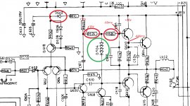
some interesting voltages, prob why its not getting any current across R626(temp pot)
Q610 is a new BD139
ignore the circles they are from a previous drawing
i feel i am close now with this.
the other channels idle is still stable at 15mv
The voltages could show a problem. You need to look at all four base/emitter voltages.
Negative 446 millivolts on the NPN output would imply that the emitter should be at almost negative 1 volt in order to preserve the correct junction polarities and yet if you have a lowish offset of 0 to 100mv then that isn't happening.
You need to check all four transistor voltages and check the resistors are OK.
What is the voltage across the diode pack? You have to see what that is and whether it is enough to bias the stage correctly. It needs around 2.5 volts across the pack.
i currently still have this shorted out(does/would this make a difference to the figures? i thought it might)
im going to test it tomorrow as you suggested to make sure its ok, as i will the other one(which i connected back for now)
im going to test it tomorrow as you suggested to make sure its ok, as i will the other one(which i connected back for now)
Yes indeed it makes a difference. You will not achieve any bias current at all with it shorted.
Try this and see if you understand it better. Have a play with the bias voltage generator and look at the current in the 0.22 ohm.
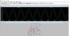
With zero bias voltage we get crossover distortion. Can you see why there is distortion? It is because the input voltage has to overcome the 0.6v (approx) B-E turn on voltage of each transistor. So there is a 'dead band' of -/+1.2 volts where the output stage does not respond. Time passes and no output voltage occurs until the input voltage has overcome that 1.2v needed (0.6 for each transistor in the upper and lower halves) for them to conduct.
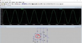
With a bias voltage of 2.9 volts we have bias current of 28 milliamps flowing. The distortion has gone. Even a milliamp or two is enough to reduce the distortion. This bias voltage (across the diode pack) brings each transistor up to and just beyond the point of conduction. The 'dead band' has gone and it can respond to very small input voltages.
Try cutting the V_Bias voltage out of the sim and putting four diodes in there instead.
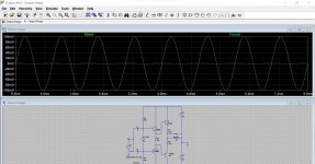
Next try making the bias zero again and this time reduce the input voltage to just 1 volt. Look at the output voltage noting the scale. Now turn the bias up again. Whoa... big big difference 🙂
Note... the distortion produced by the complete amp would be nothing like as bad as here because the output stage is enclosed within the overall global feedback loop. That reduces the distortion by a massive amount.
Try this and see if you understand it better. Have a play with the bias voltage generator and look at the current in the 0.22 ohm.
With zero bias voltage we get crossover distortion. Can you see why there is distortion? It is because the input voltage has to overcome the 0.6v (approx) B-E turn on voltage of each transistor. So there is a 'dead band' of -/+1.2 volts where the output stage does not respond. Time passes and no output voltage occurs until the input voltage has overcome that 1.2v needed (0.6 for each transistor in the upper and lower halves) for them to conduct.
With a bias voltage of 2.9 volts we have bias current of 28 milliamps flowing. The distortion has gone. Even a milliamp or two is enough to reduce the distortion. This bias voltage (across the diode pack) brings each transistor up to and just beyond the point of conduction. The 'dead band' has gone and it can respond to very small input voltages.
Try cutting the V_Bias voltage out of the sim and putting four diodes in there instead.
Next try making the bias zero again and this time reduce the input voltage to just 1 volt. Look at the output voltage noting the scale. Now turn the bias up again. Whoa... big big difference 🙂
Note... the distortion produced by the complete amp would be nothing like as bad as here because the output stage is enclosed within the overall global feedback loop. That reduces the distortion by a massive amount.
Attachments
i didnt want to connect it then find it blew it all up again, and ive worked too hard with this to let that happen.
ok i will have a look.so should i re connect the diode tomorrow?
ok i will have a look.so should i re connect the diode tomorrow?
Be sure to use the bulb.
There is always a risk, all you can do is minimise it. You could fit the diode pack and also add a preset across it. Begin with the preset at zero ohms and its just the same as with the pack shorted. Increase the resistance and the pack takes over more and more. A 4k7 or 5k preset might be a suitable value. Perhaps even a lower value to begin with like a 2k.
There is always a risk, all you can do is minimise it. You could fit the diode pack and also add a preset across it. Begin with the preset at zero ohms and its just the same as with the pack shorted. Increase the resistance and the pack takes over more and more. A 4k7 or 5k preset might be a suitable value. Perhaps even a lower value to begin with like a 2k.
Yes indeed it makes a difference. You will not achieve any bias current at all with it shorted.
Try this and see if you understand it better. Have a play with the bias voltage generator and look at the current in the 0.22 ohm.
With zero bias voltage we get crossover distortion. Can you see why there is distortion? It is because the input voltage has to overcome the 0.6v (approx) B-E turn on voltage of each transistor. So there is a 'dead band' of -/+1.2 volts where the output stage does not respond. Time passes and no output voltage occurs until the input voltage has overcome that 1.2v needed (0.6 for each transistor in the upper and lower halves) for them to conduct.
With a bias voltage of 2.9 volts we have bias current of 28 milliamps flowing. The distortion has gone. Even a milliamp or two is enough to reduce the distortion. This bias voltage (across the diode pack) brings each transistor up to and just beyond the point of conduction. The 'dead band' has gone and it can respond to very small input voltages.
Try cutting the V_Bias voltage out of the sim and putting four diodes in there instead.
Next try making the bias zero again and this time reduce the input voltage to just 1 volt. Look at the output voltage noting the scale. Now turn the bias up again. Whoa... big big difference 🙂
Note... the distortion produced by the complete amp would be nothing like as bad as here because the output stage is enclosed within the overall global feedback loop. That reduces the distortion by a massive amount.
yes i do see, this is why i asked if the diode pack made a difference.ive been sitting in the garden looking at all the voltages i took and just couldnt see how the hell those transistors were going to get turned on, so this does make sense.
the the voltage is almost getting 'lost'throught the rest of the circuit?
the sine waves on the first diagram, im not realy familiar with this part yet.is the distotion represented by the odd shaped blue wave?
Yes, that distortion is typical of 'crossover distortion' that effects all amplifier output stages like this one (Class B or AB). The green sine is the input and the blue is the output. It is always worse at low level because that is exactly the region where the transistors are not able to conduct if they are not biased.
This is with 100mv applied to the input and with no bias. The output is missing altogether because the small input voltage can not turn the transistors on. If you set even a small bias then things would improve.
Tomorrow......
This is with 100mv applied to the input and with no bias. The output is missing altogether because the small input voltage can not turn the transistors on. If you set even a small bias then things would improve.
Tomorrow......
Attachments
The poly caps are almost certainly OK, the black is from the heat of the resistors causing discolouration/contamination like you get on a white wall behind a radiator.
The diode packs can be tested up to a point but it won't tell you if they are intermittent (unless it actual fails while testing).
They should read open circuit one way around but the other way around with a four diode package is to many to read on most meters on the diode range.
Remember the meter measures the voltage at the probes when you diode test and so four diodes generates around 2.5 volts drop which might be outside what a particular meter can read on diode test range.
So you do it the old fashioned way and measure the voltage across them under a known test condition by passing a fixed current through them.
9 volt battery and series resistor to limit current. 9 volts less 2.5 volts is 6.5 volts. Lets test at say 2 milliamps. So you need a 6.5/0.002 value resistor. Use the nearest value you have. You can safely go up to about 10 milliamps I would think so you can test at different currents.
so off a 9v(8.7v) battery and a 1k in series resistor im getting 6.6mv across the diode which is about what i worked it out it should be, if i did it right of course
I'll let you work that one out 🙂
could i use a 5k trimmer and set it at 0, then gradualy increase it, i could monitor it that wayBe sure to use the bulb.
There is always a risk, all you can do is minimise it. You could fit the diode pack and also add a preset across it. Begin with the preset at zero ohms and its just the same as with the pack shorted. Increase the resistance and the pack takes over more and more. A 4k7 or 5k preset might be a suitable value. Perhaps even a lower value to begin with like a 2k.
i havent stopped using the bulb while testing.i only take it off the bulb once im 100% sure its ok.
Last edited:
You can try a 5k. All the action (if there is going to be any) will probably be in the first few degrees of rotation so turn it very slowly.
ok so i think this is as far as we can go
idle left 15mv
idle right 15mv
centre right -9mv
centre left +10mv
i cant get it any closer with the resistor values i have and there is no way to fit a pot, its just too close for comfort under there and im not going to risk it.
no room ontop either, way too tight.
it lives!!!!!!
idle left 15mv
idle right 15mv
centre right -9mv
centre left +10mv
i cant get it any closer with the resistor values i have and there is no way to fit a pot, its just too close for comfort under there and im not going to risk it.
no room ontop either, way too tight.
it lives!!!!!!
Last edited:
- Home
- Amplifiers
- Solid State
- NAD 3030 in a mess