they are very easily found (k1058 and J162) in C-audio PA amplifiers which are also easily found (broken down, for parts) on the second-hand market for a handful of cherry stems.
^ Yes, although I like new ones though 😉 not pre
The lateral mosfets are certainly still available as new product, in a plastic TO247 package branded Exicon from your local UK supplier, Profusion PLC. http://www.exicon.info/
As discussed, laterals were originally available only in TO3 format and from Hitachi. All serious power transistors were in that familiar format long, long ago but all known TO3 lateral mosfet product is now EOL , while the remaining plastic pack version range marketed by Exicon, has been trimmed back to just one N & P pair i.e. ECX10N20 and ECX10P20. These are probably still Semelab UK product so support them already or lose them too 😉 http://www.exicon.info/news/end-of-an-era-for-to3-lateral-mosfets/
As discussed, laterals were originally available only in TO3 format and from Hitachi. All serious power transistors were in that familiar format long, long ago but all known TO3 lateral mosfet product is now EOL , while the remaining plastic pack version range marketed by Exicon, has been trimmed back to just one N & P pair i.e. ECX10N20 and ECX10P20. These are probably still Semelab UK product so support them already or lose them too 😉 http://www.exicon.info/news/end-of-an-era-for-to3-lateral-mosfets/
Last edited:
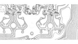
so this is how i see it if you want to do it properly, or something like this, there isn't a lot of room here to play ball.
you could easily do it with protected leg extensions, but i wouldn't be interested in doing that it would look rubbish, the only thing that i need to do is look at how the heat dissipation can be improved, and the attached is, at the moment an idea in development.
it can be done and its a lot of work, but it would be good after it was finished
Attachments


Its hard to visualise without having one in front of me... you know what should be doable and what would work though 🙂 I think I see how you mean it would look though.
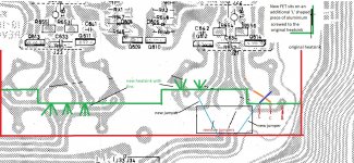
One other thing, the two vbe multipliers that bolt to the heatsink would no longer need to do so. they would be free standing and not in contact with the heatsink. Lateral FET's have a negative temperature coefficient above around 100ma or so and that means they are not prone to thermal runaway.
One other thing, the two vbe multipliers that bolt to the heatsink would no longer need to do so. they would be free standing and not in contact with the heatsink. Lateral FET's have a negative temperature coefficient above around 100ma or so and that means they are not prone to thermal runaway.
That's not a problem I'll stand them up, should be fine I just need you to confirm that I am getting the ones in the previous postsIts hard to visualise without having one in front of me... you know what should be doable and what would work though 🙂 I think I see how you mean it would look though.
One other thing, the two vbe multipliers that bolt to the heatsink would no longer need to do so. they would be free standing and not in contact with the heatsink. Lateral FET's have a negative temperature coefficient above around 100ma or so and that means they are not prone to thermal runaway.
Yes those are the ones, the N and P channel devices.
Just remember this is uncharted territory... I think it should work and work well... but it is untried at this point 🙂 Some of the resistor values around the vbe multiplier will need altering, possibly using a preset at first and then deciding on fixed values later.
Just remember this is uncharted territory... I think it should work and work well... but it is untried at this point 🙂 Some of the resistor values around the vbe multiplier will need altering, possibly using a preset at first and then deciding on fixed values later.
OK I guessed it might not be just the outputs that would change. Outside of my comfort zone at the moment that one so I will need you to tell me what ones and values 👍Yes those are the ones, the N and P channel devices.
Just remember this is uncharted territory... I think it should work and work well... but it is untried at this point 🙂 Some of the resistor values around the vbe multiplier will need altering, possibly using a preset at first and then deciding on fixed values later.
It would be the values around here:

Which could even be simplified down to this. Having set a value the preset would be replaced by a fixed resistor or parallel pair of resistors to get the nearest value:

Which could even be simplified down to this. Having set a value the preset would be replaced by a fixed resistor or parallel pair of resistors to get the nearest value:
So rx1 Controls the current to the vbe base, in turn then that will control the voltage through the the gate resistor?
Sort of. Altering RX1 allows the conduction of the multiplier transistor to be altered. The more it turns on and the less voltage is developed across C and E and that gives us lower bias current in the output transistors.
The basic operation is very similar to the ordinary transistors, its just the voltage range across the multiplier that is different. One big difference though is that the gate does draw essentially zero current unlike the regular transistors.
The basic operation is very similar to the ordinary transistors, its just the voltage range across the multiplier that is different. One big difference though is that the gate does draw essentially zero current unlike the regular transistors.
ok well i will order the transistors
ive been reading up on mosfets and understand a bit more not
so these are enhancment(i thought this) or depletion?
ive been reading up on mosfets and understand a bit more not
so these are enhancment(i thought this) or depletion?
They are enhancement types which means they are normally off with no gate/source voltage present. These are the most common types for power devices.
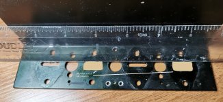
they dont have any 'N' types in stock so im going to have to get elsewhereThat's not a problem I'll stand them up, should be fine I just need you to confirm that I am getting the ones in the previous postsView attachment 1077374
- Home
- Amplifiers
- Solid State
- NAD 3020 project, strip down and upgrade.