Realmente no entiendo eso con ninguno de los que he reparado, un ligero golpe realmente. Podría instalar el circuito de silenciamiento como en la versión B, pero enen B tenía un zumbido extraño que a veces se elimina quitando y cortocircuitando los 2 FETS y actualizando los Caps C533, 532,53110 100v, pero no estoy seguro de qué tan fácil sería para silenciar, aún no lo he probado. La versión A es muy similar con algunos ajustes, pero la B es diferente en muchos aspectos. Alguien como Mooly definitivamente lo sabría, pero no creo que sea una conversión fácil.
mi próxima versión de la serie 20 incorporará el circuito phono mm/mc
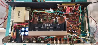
El movimiento irregular del cono de los altavoces desapareció desde que cambié los electrolitos y el puente de diodos de la fuente de alimentación. Ahora esta bien. (*) Si entendí bien, el NAD 3020 B tiene un circuito de protección/silencio incorporado y es el que me adjuntas, ok, gracias por eso. Pero necesito algo sencillo ya montado, sin modificar nada del 3020, solo conectar cables de parlantes y encenderlo, que es lo que vi en el link de AK. ¿Qué piensan todos ustedes? ¿Son eficientes o está comprando un problema? Perdón por el OT y felicidades por el trabajo, va tomando forma y se ve genial!👍
(*) Se movió dos veces hacia adentro y hacia afuera y profundamente.
https://www.ebay.com/itm/284839911443?hash=item4251c82013:g:oOsAAOSw3MhimPFl
https://www.ebay.com/itm/2940617929...zntkapbtN%2BGw%3D%3D|ampid:PL_CLK|clp:2047675
Last edited:
 EnglIsh please 🙂
The irregular movement of the speaker cone disappeared since I changed the electrolytes and the diode bridge of the power supply. Now it's okay. (*) If I understood correctly, the NAD 3020 B has a built-in protection/silence circuit and it is the one you attach to me, ok, thank you for that. But I need something simple already assembled, without modifying anything of the 3020, just connect speaker cables and turn it on, which is what I saw in the AK link. What do you all think? Are they efficient or are you buying a problem? Sorry for the OT and congratulations on the work, it's taking shape and looking great! (and)
(*) It moved twice inward and outward and deeply.
it sounds great though.ive been using it all morning, and i swear it sounds less muddy that the original
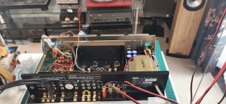

Goodness!.....gold plated bits and bobs on what was the shabbiest rear panel in the business 
Great that it sounds good - 'makes it worth all your effort and hopefully you get appropriately rewarded.
Great that it sounds good - 'makes it worth all your effort and hopefully you get appropriately rewarded.
Last edited:
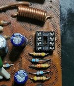
They are wurth ones, they seem ok as it happensThat looks really really good actually (and red electrolytics always look 😎)
parts are getting very expensive if you want good quality
6800uf 35x50 are £6 each+ if you want nichicon or rubycon ETC
2200 uf are even more, and getting scarce in the right sizes, proberbly due to supply problems
so the wurth ones are quite a good choice at the moment, and they look good.👍
Thanks ian, ive worked hard on thisGoodness!.....gold plated bits and bobs on what was the shabbiest rear panel in the business
Great that it sounds good - 'makes it worth all your effort and hopefully you get appropriately rewarded.
those gold connectors are £2.00 each and there is only one place to get them, this amp needs 16
it does look good though, especialy with the re wiring
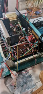
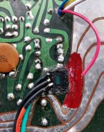
i used high temp pure copper silicone 200c cable for this, it doesnt shrink back when you are soldering👍
Last edited:
so the soft clip light modification is now complete thanks to the help from @Mooly once again, so a very big thank you goes out.
This wasnt easy to do, not so much the electronics part, but in which version of amp, as the mod is different in each case and the first version wouldnt work as it turned out to be a different version to that which the original design was based
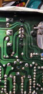
so with the op amp in place and wired into the soft clip switch-the pcb had to be drilled out to allow space for the cable/heatshrink
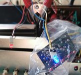
i just used an old blue one to test it.
the final colour i haven decided on yet
its an interesting excersise for me this one as im learning alot in the process and there are things i would do differently next time to make it neater
i guess thats what development is all about.
This wasnt easy to do, not so much the electronics part, but in which version of amp, as the mod is different in each case and the first version wouldnt work as it turned out to be a different version to that which the original design was based
so with the op amp in place and wired into the soft clip switch-the pcb had to be drilled out to allow space for the cable/heatshrink
i just used an old blue one to test it.
the final colour i haven decided on yet
its an interesting excersise for me this one as im learning alot in the process and there are things i would do differently next time to make it neater
i guess thats what development is all about.
Attachments

^ Thanks 🙂
And for those following all this the Soft Clip indicator ended up like this. This NAD 3020 version was significantly different to the others in the way the switching was done. This one has no change in DC conditions when the switch operates and so that needed a bit of lateral thinking to switch an LED on and off.

The opamp ended up as a 741 and the 10meg as a 3meg because these were what were available. The 6 volt supply is taken from the bargraph power meter driver supply and was done simply because a lower supply means the prebias resistor can be lower in value.
A FET opamp would allow many megohm to be used and that would lower the voltage across the two 220k's in the soft clip circuit when the soft clip was off.
The other version would have looked like this. Everything to the left of the opamp is NAD:

And for those following all this the Soft Clip indicator ended up like this. This NAD 3020 version was significantly different to the others in the way the switching was done. This one has no change in DC conditions when the switch operates and so that needed a bit of lateral thinking to switch an LED on and off.
The opamp ended up as a 741 and the 10meg as a 3meg because these were what were available. The 6 volt supply is taken from the bargraph power meter driver supply and was done simply because a lower supply means the prebias resistor can be lower in value.
A FET opamp would allow many megohm to be used and that would lower the voltage across the two 220k's in the soft clip circuit when the soft clip was off.
The other version would have looked like this. Everything to the left of the opamp is NAD:
the amp sounds great,and most definatly 'brighter'
whether thats the different transistors or a total recap,or a combo of both,not sure but i think it sounds better
the 3020 was always known for its 'warmth' and i always though it could do with brightning up a bit, maybe thats just my preference though 👍
whether thats the different transistors or a total recap,or a combo of both,not sure but i think it sounds better
the 3020 was always known for its 'warmth' and i always though it could do with brightning up a bit, maybe thats just my preference though 👍
A lot of amps are half a dB to a dB down at 20k, and when corrected sound “bright“. Even if you can’t hear past 12k. It has to do with IM products up there being produced by the tweeters themselves. Just don’t want “too bright”, which can be a result of peaking above audio - the result of marginal stability. With the TIP outputs it‘s not likely, but always possible when transistors are changed. Worst case I ever had was an incorrect lead comp cap in an amp with a hell of a lot of global NFB (Op amp input front end). Ended up with 7 dB of peaking around 100kHz. The resulting “bright” was pleasing to me with soft dome tweeters. With a Focal TC120 it would drive you out of the room. Get the cap value right, no more “bright” - even though the response at 20k was absolutely unchanged (but the 100k peak gone). Something up there was exciting that 40k breakup peak and it was NOT nice when it happened.
whether thats the different transistors or a total recap,or a combo of both,not sure but i think it sounds better
I would guess the new caps you fitted are much better than the decades old NAD originals that were used back in the day. Transistors should not effect the response at all because the overall response is determined by all the passive components and the time constants that are inbuilt into the design. Also cleaning up switches and pots, that can certainly make a difference. Its everything coming together at once.
Could very well BE the caps. Especially coupling caps with almost no voltage on them. They never really get “formed” in the first place because of lack of bias, and subject to degrade faster than if they has DC on them. Can develop tens of K ohms of ESR (often frequency dependent) and the changes over time be too small to “notice” in a high-ish impedance circuit. Except when you put in new ones.
Just give it a small signal square wave test, and see how pretty it looks. As long as you don’t see a bunch of ringing you’re good.
Just give it a small signal square wave test, and see how pretty it looks. As long as you don’t see a bunch of ringing you’re good.
so i have 2 of this version currently awaiting repair(i think i have 12 of these in various guises)^ Thanks 🙂
And for those following all this the Soft Clip indicator ended up like this. This NAD 3020 version was significantly different to the others in the way the switching was done. This one has no change in DC conditions when the switch operates and so that needed a bit of lateral thinking to switch an LED on and off.
View attachment 1076276
The opamp ended up as a 741 and the 10meg as a 3meg because these were what were available. The 6 volt supply is taken from the bargraph power meter driver supply and was done simply because a lower supply means the prebias resistor can be lower in value.
A FET opamp would allow many megohm to be used and that would lower the voltage across the two 220k's in the soft clip circuit when the soft clip was off.
The other version would have looked like this. Everything to the left of the opamp is NAD:
View attachment 1076277
If i can get the text to look ok(im not drilling the front yet untill thats sorted) maybe ill try the other version mooly see how that fairs
- Home
- Amplifiers
- Solid State
- NAD 3020 project, strip down and upgrade.