Yep, a few subtle differences there 🙂
I've all these versions but couldn't say which to use without seeing lots of details on the real amp.

I've all these versions but couldn't say which to use without seeing lots of details on the real amp.
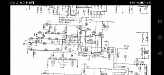
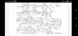
It is just ridiculous how many iterations there are of this amp 😊. With all these schematics I think you'd be able to sort of figure out what you need. That phono stage does have a couple of changes throughout the years though...
I can tell which one is which now just looking at it, sad isn't it 😔

Guys, thanks for beeing so helpfull.
It is indeed ridiculous and very confusing.
The problem I ran against is that some of caps I pulled of the board are different values then the diagram I use.
Like C401 and C402. They are 10uf in my board. On none of the diagrams they are that value.
Also C911 and C912 are 10uf values in my amp.
The kit only came with three 10uf caps and two of them are now used for C421 and C422 like on the schematics Mooly shared.
there were alot of factory mods that were never recorded
That is the big problem. It always pays to look at exactly what is fitted and order that value. When replacing do them one at a time, like for like and not just remove them all in one go first.
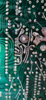
That doesn’t look normal no, they might do that on the thicker traces where there’s more current flowing. In this instance it looks like the soldermask wasn’t applied correctly. It doesn’t matter, just make sure there’s no shorts. It might be a good idea to put some pcb coating on there.
looks like they had either lost some track or just flowed a bit extra over it, ive done it before but i never put that much down,its ok though
little tip, bend your legs over a little rather than leaving them straight up, it helps to make the cap more secure on the board 😉Fortunatly I did the replacing one at a time. For a beginner its a must. Also because the markings are sometimes unreadable.
I however did not expected different versions of the same version 😁
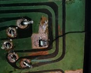
I discovered some cracks on the top of the board at the place were they tinned the traces... guess that is the reason they tinned the traces there.Is this normal? They soldered the traces...
Prob with the amp is the chassis, you can twist it, and you might notice some amps wobble with the base plate on. That's because you must put the middle 2 screws in first then the corners, but don't tighten up untill all are just tightened. So what happens is people twist the chassis with the base plate attached, and this will correct the shape, but an then crack the pcb
- Home
- Amplifiers
- Solid State
- NAD 3020 project, strip down and upgrade.