For anyone who might be interested or wondering, I waiting for delivery of the soft-start module I ordered before venturing further into the transformer thingy-do. It should be here in a day or two.
Check what current flows in the switching transistor that pulls in the relays.
You need a base current ~10% of the total relay triggering current.
You need a base current ~10% of the total relay triggering current.
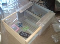
I've made little progress. I have drilled the steel cover and the heatsinks are now attached 6 screws per side. The pic shows the face plate and 1/4 round shaping the sides. The remote is bigger than I thought it would be, the IF receiver is shipped in the plastic box. The stepper motor is about the same size and the LDR board a little larger. I still need to order the Alps and the parts for the regi22 regulators. I hope to buy a Antek AS 300 24 + 24 and maybe a 100 15 + 15 for a DCB1 board. I have a Avel 15V +15V from my dead Kookabura . Maybe it should power the LDR and Darwin only and use the regi22 plan only for the parts out of the signal chain.
But that's what I liked about it. Using capacitance to keep the LDR powered while the amp shut down. To avoid it going full volume ?
Uriah, that LDR selector is kewl. I bet it's cleaner than the silver contact relays in the Darwin.
But that's what I liked about it. Using capacitance to keep the LDR powered while the amp shut down. To avoid it going full volume ?
Uriah, that LDR selector is kewl. I bet it's cleaner than the silver contact relays in the Darwin.
Attachments
Very nice and pleasingly clean. Can you explain why you transitioned to wood. Is that an appearance element? It looks very interesting.
Very nice and pleasingly clean. Can you explain why you transitioned to wood. Is that an appearance element? It looks very interesting.
I wanted the amp to match my speakers.
http://www.diyaudio.com/forums/full...ge-speaker-photo-gallery-182.html#post2791620
Making some progress. The Parasound JC-2 pre/buffer clone is up and running. On test rig with Sony Walkman to JC-2 to Hefler DH-120 to small DIY speakers. Sound so far is excellent.
Next step is to drive the JC-2 with the output of the Lighter Note. If all is OK there, I'll mount all pieces (Trans x 4, LN, JC-2, MyRefs x 2) on a project board and audition with main speakers.
Still haven't received the soft-start so the mock-up will use separate AC ins for this stage.
An externally hosted image should be here but it was not working when we last tested it.
An externally hosted image should be here but it was not working when we last tested it.
Next step is to drive the JC-2 with the output of the Lighter Note. If all is OK there, I'll mount all pieces (Trans x 4, LN, JC-2, MyRefs x 2) on a project board and audition with main speakers.
Still haven't received the soft-start so the mock-up will use separate AC ins for this stage.
A beautiful Mess
Man, I didn't even get to the LN and the MyRefs. I took an intermediate step since I had the BrianGT monoblocks and the Lightspeed already set up. Simply put the JC-2 in the system.
What I'm hearing is literally jaw dropping. At the first listening on the Sunflower speakers there was a noticeable harshness, narrow stage and a confined presentation with the new Pre.
After about six hours of use it's a whole different world. The balanced presentation is simply awesome. I heard some low pedal organ notes on a Respighi "Pines of Rome" CD that never showed up in the many years I've owned it. With the volume pot on the LS at 45% rotation instead of the 99% I was using, the full force of the large orchestra at the SPL where the conductor stands was easily achieved. I have little doubt I could blow out my speakers with this combination.
I also arbitrarily pulled out M. Jackson's "Bad" CD. Lots of electronics, heavy percussion and of course the vocals. The clarity and dynamic shifts and punch were exceptional. The bass and bass synth sounds fully enveloped the room. The highs are pulled back a bit but still sparkly and clean - not a bad thing. It's like the difference between using bright sounding silver wires and a bit warmer high quality copper.
I just can't imagine what this little gem will do with the highly modded MyRefs driven by the Light Note. Actually, the JC-2 makes the BrianGT amps sound better than a stock MyRef-C. At around $40 inc. shipping, it is an absolute steal.
Just got a reply from the supplier, Stanton at Jim's Audio - eBay, stating some customers are using it to replace preamps like the Goldmund top end offerings. Wow!
OK, here we go. I received the soft-start yesterday.
The first two pictures are the general placement close to the mains in.


This is a possible location inside the transformer can. To the left of the JC-2 is a self contained 12 VDC wall wart. I can wire it (or something similar) in but don't know if it is a good choice to power the soft-start. That wall wart can be mounted on the chassis floor near the mains in, with the soft-start above it on long stand-offs. Probablly not what the Pros would do.😱
Above the SS is the tiny power supply for my smart phone. It has USB power out, but I would love to get a handle on how it goes directly from 120VAC to 12VDC in such a small package.
The alternative would be to add a separate 12V toroid (same size as the smallest one in the pictures - mounted vertically) plus a regulator to power the Soft-start - either inside or outside the transformer can.

Just the specs on the wall wart.

This diagrams the mains in for all the major components

The last picture shows my understanding of Andrew Ts approach. Note: not clear on where to get AC for SS power source.

I see this as a base to start from and am open to, and encourage all suggestions. If creating a complete DIY configuration from scratch appears more plausible, please let us know.
Also, I have not yet actually tested whether having discrete toroids for the MyRefs truly adds to sonic performance. A reconfiguration of the shield is possible if needed.
The first two pictures are the general placement close to the mains in.
This is a possible location inside the transformer can. To the left of the JC-2 is a self contained 12 VDC wall wart. I can wire it (or something similar) in but don't know if it is a good choice to power the soft-start. That wall wart can be mounted on the chassis floor near the mains in, with the soft-start above it on long stand-offs. Probablly not what the Pros would do.😱
Above the SS is the tiny power supply for my smart phone. It has USB power out, but I would love to get a handle on how it goes directly from 120VAC to 12VDC in such a small package.
The alternative would be to add a separate 12V toroid (same size as the smallest one in the pictures - mounted vertically) plus a regulator to power the Soft-start - either inside or outside the transformer can.
Just the specs on the wall wart.
This diagrams the mains in for all the major components
The last picture shows my understanding of Andrew Ts approach. Note: not clear on where to get AC for SS power source.
I see this as a base to start from and am open to, and encourage all suggestions. If creating a complete DIY configuration from scratch appears more plausible, please let us know.
Also, I have not yet actually tested whether having discrete toroids for the MyRefs truly adds to sonic performance. A reconfiguration of the shield is possible if needed.
Last edited:

You need to show/describe what relays you are using.
You need to show the Soft Start schematic.
What colour is Mains Live?
What colour is Mains Neutral?
You need to show the Soft Start schematic.
What colour is Mains Live?
What colour is Mains Neutral?
Andrew,
This is the inlet I have been using.

Specs from Delta electronics.


As I install in chasis.

Bl-Rd colors should be reversed - I'll pull out Photoshop later.

I have not purchased the relays or resistors yet. The specs for those are what I hope will be determined here. The supplier has not yet given permission to post/publish the schematic for the soft-start. I'll try again today. (It is the one I sent you in a PM).
This is the inlet I have been using.
Specs from Delta electronics.
As I install in chasis.
Bl-Rd colors should be reversed - I'll pull out Photoshop later.
I have not purchased the relays or resistors yet. The specs for those are what I hope will be determined here. The supplier has not yet given permission to post/publish the schematic for the soft-start. I'll try again today. (It is the one I sent you in a PM).
Thought I should repost the toroid values here.
T1 = Antek AN-2222 – 200VA for MyRef A
T2 = Antek AN-2222 – 200VA for MyRef B
T3 = Antek AN-0518 – 50VA for JC-2 Pre
T4 = Antek AN-0112 – 10VA for Lighter Note
T1 = Antek AN-2222 – 200VA for MyRef A
T2 = Antek AN-2222 – 200VA for MyRef B
T3 = Antek AN-0518 – 50VA for JC-2 Pre
T4 = Antek AN-0112 – 10VA for Lighter Note
as far as the mains feed to the transformer primaries are concerned, the soft start does not need Neutral. The soft start is a resistance inserted into the primary feed and after a short delay that resistance is shorted across with the relay. Since you are planning to locate the reays and resistances remotely then the SS does not need Live either.
The SS needs a low voltage input probably single polarity DC and two tappings "out" to drive the relays.
Is LN, the low voltage supply that is NOT needing a SS?
I need to see what is on the SS and on the relays to offer accurate and detailed advice on where wires go.
Can you change the wire colours?
post72
the description on the middle pic showing the pins of the IEC seems wrong.
The male pins must not be Live (source of Mains power). The female receptacles (that receive the individuals pins) must be Live. This is so straying fingers cannot touch the mains supply lins.
The diagram describes the opposite.
The shroud around the socket is not normally referred to as female. It's the pins that get that designation.
Or
Is the USA and Canada different?
Last edited:
Reply from Connexelectronic -
Hi Bob,
sorry for late reply, i was out of SZ for more than one week, during CNY holiday, and i had internet access just twice in all this time.
sure, can post the schematic, there is no rocket science there, i will try to follow the thread, i saw some very interesting posts in that thread, and it might be useful for others too.
there is no unique best-fitted solution for a soft-start circuit, there are lots of different ways how can be implemented, and the current boards which i made are among the simplest and cheapest way to do this. i was considering to develop a more complex circuit, with true-soft start, using an MCU to control the phase angle of an SCR while monitor the voltage and current ramp, or using a MOS-FET or IGBT bridge in a PWM circuit in series with the transformer. this circuit will be so complex, that it's complexity and cost might not be justified for nearly 1-3 seconds of use, 2-3 times per day.
but who knows, if someone could consider this thing useful, i could continue working on this.
This is the box in my house. White = common/neutral, Black = hot/live 120VAC, Red = hot/live 220VAC, Green/Copper = earth ground.

Standard 3-prong wall socket.

Black and white reversed after module. I will swap to match what's in the service box.

I think this is now correct, allowing the hot to be switched.

.jpg")
I'm going to contact Uriah to find out what is the minimum allowable PS for the LN.
Standard 3-prong wall socket.
Black and white reversed after module. I will swap to match what's in the service box.
I think this is now correct, allowing the hot to be switched.
I'm going to contact Uriah to find out what is the minimum allowable PS for the LN.


using the schematic, it looks like the LV transformer is on board.
You don't need an extra transformer to power the soft start.
This transformer almost certainly receives it's power direct from the mains. You need Live and Neutral into the SS.
It looks like K1 is the Standby/ON switch. This allows power to be applied to your amplifier chassis without a Mains ON/OFF switch. The removeable IEC plug or a back panel OFF switch can be used.
K2 is the bypass for the soft start resistors Th1//Th2. Do not connect thermistors in parallel. Resistors can be wired in parallel.
I am not sure but it looks like the two relays are swapped.
Is PIN4 of J1 the Live feed? It should be, that's where the fuse is.
Then that makes this a neutral switched soft start.
or
Is PIN1 J1 the Live input? In which case the fuse is in the wrong ******* place.
It looks like J2 is your LV ON/OFF/Standby control.
Let's get this far confirmed before we look at soft starting the individual transformers.
Last edited:
- Status
- Not open for further replies.
- Home
- Amplifiers
- Chip Amps
- MyRef Integrated Solutions