Finally i have some good speakers (XTZ 99.26) now and i can say the alternate config of RC (390R-220uf) sounds much better, better imaging and details. Maybe can be fatigueing on some "bright" speakers but not on my ribbon tweeters.
Thanks for reporting 🙂
I've read that such speakers are a bit difficult to drive, the FE drives them well?
Until a certain point when FE starts to produce some cracking sound in the tweeters, the same behaviour experienced with Spedors SA-1 even harder to drive.
I already shared this experiences that i had with FE and i dont know if it's the Spike protection or not.
Maybe i will find some time to resolder the old MyREFC to make a comparision.
Anyway for regular and even a bit loud listening levels in my apartment MyRef is enough powerful.
I have already broke some audiophile hearts here in Bucharest with MyRef FE 🙂 and in a direct comparition on some Xavian 250 owner of an Anthem 225 said that he likes a lot dinamics and refinement of MyREF over his Anthem.
Last edited:
No gain, only PGA2310>DCB1>MyREF
See also here my preamp: http://www.diyaudio.com/forums/anal...r-volume-controlers-source-selections-76.html post #757
See also here my preamp: http://www.diyaudio.com/forums/anal...r-volume-controlers-source-selections-76.html post #757
I've gone back to post801. No post found.................... i can say the alternate config of RC (390R-220uf) sounds much better, better imaging and details..................
Can you link to where you bring up discussion of the RC?
i don't understand your question Andrew.
The discussion about alternate RC config appared since latest pcb layout where you can install 390R and 220uf in old way and alternate to make comparitions.
On my previous low quality speakers it was hard to hear the difference.
The discussion about alternate RC config appared since latest pcb layout where you can install 390R and 220uf in old way and alternate to make comparitions.
On my previous low quality speakers it was hard to hear the difference.
post757 discussing keeping the resistors on the +IN Pin and -IN Pin as close to the PINs as possible.
And the following posts?
And the following posts?
this part of post 757:
Basically you mount R10 in C9 position and C9 in R10 positions so to have C9 bounded to 0V ground.
1) C9 is quite good an electrostatic antenna ==> exchange positions of R10 and C9 and minimize trace length on LM318 -IN (Pin3).
Basically you mount R10 in C9 position and C9 in R10 positions so to have C9 bounded to 0V ground.
Ah,
This is what I brought up a long time ago.
Probably not this Thread.
The resistors must be right next to the -IN & +IN Pins.
Is Atupi reporting that he has moved the resistor closer to the -IN Pin?
And the result is improved sound quality?
Is he reporting a change to the value of the RC time constant?
Or, has he retained the 86ms RC? 390r & 220uF = 86ms
The resistors must be right next to the -IN & +IN Pins.
KSTR's suggestions should have the goal of 'achoring' one of C9's plates to ground so to pickup less noise.
Is Atupi reporting that he has moved the resistor closer to the -IN Pin?
And the result is improved sound quality?
Not exactly, the RC boards have the option to mount C9/R10 in both ways.
Yes, the sound subjectively improves.
Is he reporting a change to the value of the RC time constant?
Or, has he retained the 86ms RC? 390r & 220uF = 86ms
Only positions are swapped, values are My_Ref's default ones.
Does swapping the locations of C & R put the resistor closer to the -IN Pin?
I think the answer is "yes".
I do not agree that anchoring one of the capacitor plates to Signal Ground has a more significant effect. I would argue that the anchoring has an insignificant effect.
I would also argue that a bigger effect would be brought about by physically moving the resistor to be actually on the -IN Pin rather than 15mm away from it.
Does swapping the locations of C & R put the resistor closer to the -IN Pin?
I think the answer is "yes".
Absolutely.
I do not agree that anchoring one of the capacitor plates to Signal Ground has a more significant effect. I would argue that the anchoring has an insignificant effect.
I don't know but also Mauro found some merit in it.
I would also argue that a bigger effect would be brought about by physically moving the resistor to be actually on the -IN Pin rather than 15mm away from it.
Can you elaborate a bit?
Thanks 🙂
Thanks Dario for clariying the discussion.
You're welcome 🙂
the -IN Pin and to a lesser extent the +IN pin are very suceptible to parasitics, especially capacitance.
The further away the resistor, the longer the trace (and component if swapped the wrong way around). That longer trace has more parasitics than a 1mm trace to an adjacent resistor.
That is the problem that must be avoided in laying out any opamp or power amp traces.
Minimise parasitics on the +IN and -IN Pins.
I am sure I have explained this more than a few times and I am also pretty sure I have argued this on a MyRef Thread.
the -IN Pin and to a lesser extent the +IN pin are very suceptible to parasitics, especially capacitance.
Sure, now I understand, thanks 🙂
I've taken it in in account (see the IN- trace) but it's more difficult for IN+, what would you have done differently?
Attachments
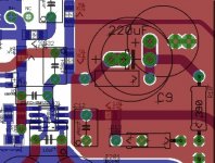
I can't make out the traces well.
But I read it as capacitors near the -IN & +IN Pins.
It should be resistors next to the Pins.
100r, or 200r, smd at the Pins or under the PCB using PTH for shortest (pin to resistor) routes would allow anything to be hung on the other side of the resistors.
But I read it as capacitors near the -IN & +IN Pins.
It should be resistors next to the Pins.
100r, or 200r, smd at the Pins or under the PCB using PTH for shortest (pin to resistor) routes would allow anything to be hung on the other side of the resistors.
no updates for 3 days, let me fix that...
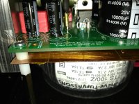
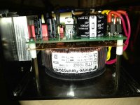
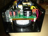
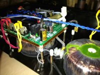
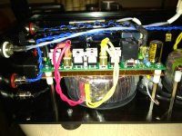
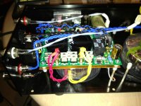
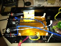
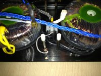
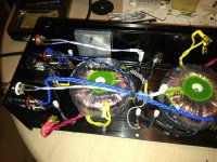
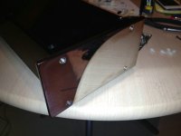
at last, I have added copper shields, a grounding wire and desoldered few sockets! WOW...The sound has dramatically improved and the soundstage became extremely wide and deep, moreover, I felt as the output power has doubled or even more 😀 kidding! no improvements here, it's already good and no hum from toroids as I reported earlier, so just aesthetic addons.
some pics below:
Attachments
-
 IMG_0053.jpg708.8 KB · Views: 150
 -
 IMG_0052.jpg672.5 KB · Views: 145
 -
 IMG_0051.jpg642.2 KB · Views: 142
 -
 IMG_0049.jpg599.7 KB · Views: 147
 -
 IMG_0048.jpg689.5 KB · Views: 151
 -
 IMG_0047.jpg577.4 KB · Views: 159
 -
 IMG_0045.jpg665.5 KB · Views: 243
 -
 IMG_0044.jpg742.3 KB · Views: 259
 -
 IMG_0043.jpg707.4 KB · Views: 273
 -
 IMG_0055.jpg376.1 KB · Views: 154
- Status
- Not open for further replies.
- Home
- Amplifiers
- Chip Amps
- My_Ref Fremen Edition RC - Build thread