Class A is supposed to be better simply for the lack of crossover distortion.
How many milliwatts of classA operation does the FE runs? My guess is about half a watt.
Bob, you are right: in the technical presentation of the My_ref (from Mauro Penasa), it was explicitly written that the topology of My_ref (in brief: voltage gain given by an opamp + a "current stage" + total negative feedback) has unique characteristics. They can be seen as an "evolution" of MF A370, at most.
I do not think that it will never be possible to push the My_ref design to be like class A amplifiers, that usually have no negative feedback at all, or just local one. In few words: in class A amplifiers the performances are obtained with "linearity": everything must be as linear as possible. While Penasa's design is taking components that has non-linearities (call them THD or whatever) and it is hiding them by a very smart use of phase compensations and circuit configurations.
Penasa wrote that he was explicitly trying to obtain a sonic signature as the one of SE tube amplifiers (at least for rev.A). I maybe wrong but I guess that he worked on phase compensations and feedback+feedforward techniques just to implement the "picture" he has in his head.
Regards,
Daniele
I also think that it was voiced by the late Penasa, and refined by Dario.
Still, the measured specs are really good and THD and IMD do not really play a role in the character. More like the interaction of the current "well" with the speakers. It's not a current drive, it's something else, which works very very well in all but the most hard to drive crossovers.
I have abstained so far to voice my opinion about its sound, I want to finish to read all threads to understand more, but it definitely has some qualities seen in class A and tube designs.
(220 pages to go 😉 )
How many milliwatts of classA operation does the FE runs? My guess is about half a watt.
From what I can understand it depends entirely on the LM318.
How much Class A operation has the LM318? I really don't know...
Thanks! It is a Khozmo MKII 10k with MK132s.
How do you like the khozmo? Someone else tried it, or even better compared to a TVC (glasshouse or better)?
How many milliwatts of classA operation does the FE runs? My guess is about half a watt.
From what I can understand it depends entirely on the LM318.
No. It depends on the LM3886. Specifically, it depends on the quiescent current of the output stage, which is not called out as a data sheet spec specifically. You can get some idea from the information that is given about the total quiescent current/supply current of the chip.
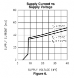
The spec table in the LM3886 data sheet reveals that the quiescent current of the LM3886 is 50 mA (typical). Digging a little deeper (Figure 6) reveals that the supply current varies with supply voltage and device temperature. At ±10 V, the supply current is about 34 mA (70 ºC device temperature) and at the ±35 commonly used in the MyRef, it's 45 mA (70 ºC device temperature).
If we for a second assume that all of the supply current goes to the output stage (which it doesn't, but the majority probably does), we can figure out how much power the amp would be able to deliver in Class A. The LM3886 will enter Class AB (i.e. exit Class A) once its output current exceeds its bias/quiescent current.
At ±10 V: Iout_peak = Isupply = 34 mA
Pout = Iout_RMS2*R
--> Pout = (Iout_peak/sqrt(2))2*R = Iout_peak2*R/2
--> Pout = 0.0342*8/2 = 0.00462 = 4.62 mW
At ±35 V: Pout = 0.0502*8/2 = 0.010 = 10 mW
So not much power in Class A.
Note that this is for typical silicon, i.e. an average chip pulled off the assembly line. As the supply current spec indicates, the supply current does vary from device to device as part of normal device variation. The maximum supply current is specified (85 mA @ 25 ºC device temperature) but the relevant number for the output power calculation is the minimum supply current, which is not specified.
Tom
Attachments
And this is valid equally so for all LM3886 designs. Except if someone tries to pull the chip more in class A operation. Heating up evereything and sacrificing output power.
But the original question is missing the target, in my opinion. We should ask not how, but what is achieved. How much crossover distortion can be releived at low output levels from the amp?
The response can be searched in the already executed tests. Not in the THD+N figures, because at low levels the noise dominates. We saw that THD figures are the same or slightly lower, than at high level output staying always at around~0,0001%. More importantly the harmonic structure is dominated by the low few harmonics, and not the usual "picket fence" structure, the typical sign for crossover distortion.
It all is merit of the LM3886 designers. The chip does show signs of crossover distortion, at very high frequencies, well above the audio range.
Ciao, George
Last edited:
Dario, at a certain point we had been discussing about the internal workings of the topology, and the conclusion was that the control opamp (mostly LM318) stays mostly in class A operation, because of the low load that it's output stage has to serve.
Ciao, George
Ciao, George
But the original question is missing the target, in my opinion. We should ask not how, but what is achieved. How much crossover distortion can be releived at low output levels from the amp?
The response can be searched in the already executed tests. Not in the THD+N figures, because at low levels the noise dominates. We saw that THD figures are the same or slightly lower, than at high level output staying always at around~0,0001%. More importantly the harmonic structure is dominated by the low few harmonics, and not the usual "picket fence" structure, the typical sign for crossover distortion.
It all is merit of the LM3886 designers. The chip does show signs of crossover distortion, at very high frequencies, well above the audio range.
Ciao, George
Yes, my concern regards the high frequencies. With certain tracks I felt a very slight harshness at output levels which were around 0,5W. That is with Dario SOTA build. Low level distortion concerns me way more than high level ones.
Reading about the different compensation that madisonsears did (around post 1500) made me think about this and XO distortion is the first thing that came to my mind. I have still to discover if anything was changed and if the episode was isolated.
I'll also have another look at the measurements linked in the pdf (yours?).
Pardon me, the automatic answer machine has gone off and I just can't stop it..
"Try a different opamp..try a different opamp.."
☺☺
Seems I'm joking but it comes from a 'having heard that' sensation..
Ciao, George
"Try a different opamp..try a different opamp.."
☺☺
Seems I'm joking but it comes from a 'having heard that' sensation..
Ciao, George
Pardon me, the automatic answer machine has gone off and I just can't stop it..
"Try a different opamp..try a different opamp.."
☺☺
Seems I'm joking but it comes from a 'having heard that' sensation..
Ciao, George
Uhh... this looks like a bigger mod than just trying 15pF at C34 (provided the current rev PCB have same numbering).
A couple candidates?
And this is valid equally so for all LM3886 designs. Except if someone tries to pull the chip more in class A operation. Heating up evereything and sacrificing output power.
True that.
But the original question is missing the target, in my opinion. We should ask not how, but what is achieved. How much crossover distortion can be releived at low output levels from the amp? The response can be searched in the already executed tests. Not in the THD+N figures, because at low levels the noise dominates.
Exactly!
The THD+N plots are meaningless as, unless something is broken, they mostly show the noise and residual THD of the measurement system. Measurements of THD are meaningful if you can find a source with low enough THD. Victor's oscillator (floating around here) is one option but it can be rather moody to work with. I'm working on getting a filter going so I can use the source in my APx525 which "only" offers -112 dBc THD. 🙂
More importantly the harmonic structure is dominated by the low few harmonics, and not the usual "picket fence" structure, the typical sign for crossover distortion.
It all is merit of the LM3886 designers. The chip does show signs of crossover distortion, at very high frequencies, well above the audio range.
I find that the harmonic structure and the THD vs frequency to be indicative of the listening experience. I agree with your notion that low order (2nd, 3rd, 4th, preferably in descending magnitude) harmonic distortion sounds better than a forest of THD spurs.
I also find that having the THD stay below audible (say -60 to -80 dBc) across the audio range is key to a good listening experience. The 'naked' LM3886 does creep above that towards the high end, especially if you use higher gain. That's just a function of the loop gain rolling off.
Finally, the IMD is important as well. Siegfried Linkwitz speculates that the 1k+5.5k IMD is especially important as most of the IMD products end up in the frequency range where the ear is the most sensitive (look up the Fletcher-Munson curves if you're interested). I think that has something going for it. I use a 32-tone test signal for IMD testing my amps. That's as close to music as it'll get with a deterministic signal, I think.
Finally, the amp needs to have enough slew rate to be able to produce at least a 20 kHz sine wave cleanly rail-to-rail. Otherwise, we end up with That 1970ies Sound which nobody seemed to care much for. Ask anyone who's ever used an LM741 for a line stage and they'll tell you all about it. 🙂 Thankfully, that's a solved problem now, so unless the circuit designer screws up, we don't have to worry about it these days.
Tom
Victor's oscillator (floating around here) is one option but it can be rather moody to work with. I'm working on getting a filter going so I can use the source in my APx525 which "only" offers -112 dBc THD. 🙂
A few days ago I have found an extremely cheap device (80 bucks) which produce a very clean 1khz, according to specs:
-Frequency: typically within plus or minus 1% of 1 kHz
-Distortion is very low, typically less than 2 parts per million (0.0002%), typically only 2nd harmonic is visible.)
-Maximum Output Level: 1.5 Volts RMS, adjustable
-Output impedance: 100 Ohms minimum to 2.5K maximum (depends upon level control setting)
it's sold here:
Akitika Store
For beginners like me, without desire or means to invest in a AP2700, it could be a good start. Wish it was a 20khz oscillator though.
I find that the harmonic structure and the THD vs frequency to be indicative of the listening experience. (...) The 'naked' LM3886 does creep above that towards the high end, especially if you use higher gain. That's just a function of the loop gain rolling off.
Finally, the IMD is important as well. Siegfried Linkwitz speculates that the 1k+5.5k IMD is especially important as most of the IMD products end up in the frequency range where the ear is the most sensitive (look up the Fletcher-Munson curves if you're interested). I think that has something going for it. I use a 32-tone test signal for IMD testing my amps. That's as close to music as it'll get with a deterministic signal, I think.
I cannot agree with you more.
Finally, the amp needs to have enough slew rate to be able to produce at least a 20 kHz sine wave cleanly rail-to-rail. Otherwise, we end up with That 1970ies Sound which nobody seemed to care much for. Ask anyone who's ever used an LM741 for a line stage and they'll tell you all about it. 🙂 Thankfully, that's a solved problem now, so unless the circuit designer screws up, we don't have to worry about it these days.
This is the chipamp weakness IMO.
I wonder if a higher slew rate is really needed (to produce a clean 20khz square wave), or the typical recommendation of 80us/V.
It's a subject worth of more investigations from my part. Speed seems not to be lacking from listening tests. And the Spectral-type amps have other drawbacks that hinder that advantage (assuming it can be heard).
Please bear in mind that with the way the my_ref_fe already sounds we are nitpicking. Haven't heard a modulus yet, but I'm sure it sounds good, albeit different.
Uhh... this looks like a bigger mod than just trying 15pF at C34 (provided the current rev PCB have same numbering).
A couple candidates?
If you have a good working board, the opamp mod isn't that bad. I think you will like it.
Prime candidates are the ADA4627, OPA827, and to a lessor degree OPA627. The 627 is very expensive and, as I understand it, the ADA4627 and OPA827 are a bit better.
Personally, I've only tried the ADA4627, but it is a nice step toward clarity.
Jac
Telstar,
You asked for a hint.. now I would put forward that it is sometimes (always) difficoult to separate causes and consequences.. if problems heard are from the amp itself or only because (finally) somebody tells the truth..and now you hear problems coming from the source.
The first and major offender in this aspect (harshness) are usually digital sources - - but I have heard also analogue setups with shitty pickups..
This so much so that it's practically almost sure that your source does it up to a certain level. There are ones with smaller contribution - - not very frequent..
So, having cleared this part: If something, then as a hint I would look into swap out all of the Susumu Rg parts fron the amp. We / I have done it many times and I gathered the sensation that a certain 'ruvidity' had gone with them..
Mind You, small!!
Armtrans caps are merciless. Not harsh but not forgiving..
And the chip.. an ADA4627 is a tube amp installed in your module..
Ciao, George
Last edited:
Regarding an low distortion, this might be of interest to someone willing build their own oscillator.
http://www.nanovolt.ch/resources/low_distortion_oscillators/pdf/low_distortion_oscillator_design.pdf
Jac
http://www.nanovolt.ch/resources/low_distortion_oscillators/pdf/low_distortion_oscillator_design.pdf
Jac
The first and major offender in this aspect (harshness) are usually digital sources.
(...)
So, having cleared this part: If something, then as a hint I would look into swap out all of the Susumu Rg parts fron the amp. We / I have done it many times and I gathered the sensation that a certain 'ruvidity' had gone with them..
Mind You, small!!
Armtrans caps are merciless. Not harsh but not forgiving...
No idea which parts are in Dario ultimate BOM. There's a lot of vishay naked that's for sure 😀
It wasn't coming from the source, that is my pcm1704 DAC, in comparison (by memory) with my firstwatt F3.
A few other amps have transited in my listening place in the last few months, which were all inferior to the myref, the closest being Classé CAP-2100, used as integrated.
But... is also possible that it was coming from the source intended as the recording itself, which the myref was just passing by, being two orders lower distortion (although at 0,1-0,5W I'm not so sure).
I dont remember Bob to say anything about sweetness and such with his comparison with tube amps. But he has never perceived any harshness from the myref.
I have put myself in list for the next GB. When time comes, I may either resell the boards or play the parts game (opamp included). I have also to say that after my chat with Dario, I mostly agree with his way of thinking and tweaking.
If you have a good working board, the opamp mod isn't that bad. I think you will like it.
Prime candidates are the ADA4627, OPA827, and to a lessor degree OPA627. The 627 is very expensive and, as I understand it, the ADA4627 and OPA827 are a bit better.
Personally, I've only tried the ADA4627, but it is a nice step toward clarity.
The one that George just called a tube amp? 😉
Looks like your 4 ears are different.
Noted. For future (eventual) experiments.
I have put myself in list for the next GB. When time comes, I may either resell the boards or play the parts game (opamp included). I have also to say that after my chat with Dario, I mostly agree with his way of thinking and tweaking.
I can report my experience: i built a first my_ref 2 years ago, LM318 opamps onboard, but some z-foil here and there (as suggested by Dario). It was good, very good, for a chipamp (it was comparable with Modulus at that time).
Then i swapped LM318 for ADA4627 and.. believe me... it was like buying an amp twice the price level! Particularly when used as integrated with a pot.
Then i swapped ADA4627 for OPA827 and put in some other z-foil at the pump, some glass caps in selected positions and hexfred diodes (Joseph K suggestions, except hexfreds - you can use Cree sit and they should be even better).
Oh my god! Incredible! The SQ improvement is huge! Now my FE sounds like a true hiend amp! I say TRUE HIEND.
No harshness, believe me, neither a little bit!
Most important, there are plenty of components where you can act to adjust the sound to your taste and plenty of good people to give you suggestions in this projects. That cannot be said about more "closed" commercial projects.
So, if i was you, i wouldn't think twice about getting a pair of my_ref boards and doing what's needed to get the very best out of this project. The reward is exceptional!
Last edited:
- Home
- Amplifiers
- Chip Amps
- My_Ref Fremen Edition - Build thread and tutorial