I can report my experience: i built a first my_ref 2 years ago, LM318 opamps onboard, but some z-foil here and there (as suggested by Dario). It was good, very good, for a chipamp (it was comparable with Modulus at that time).
Then i swapped LM318 for ADA4627 and.. believe me... it was like buying an amp twice the price level! Particularly when used as integrated with a pot.
Then i swapped ADA4627 for OPA827 and put in some other z-foil at the pump, some glass caps in selected positions and hexfred diodes (Joseph K suggestions, except hexfreds).
Oh my god! Incredible! The SQ improvement is huge! Now my FE sounds like a true hiend amp! I say TRUE HIEND.
Hi Luca,
Dario's build (audiophile BOM) already sounds highend. It's in the 5k-10k ball park. I think the lm318 is the OPA used, if that's still the recommended one.
Looks like more people did opamp rolling. Interesting. I am worried about stability, though. I'm still at page170 of the thread. Need more days to get to this point i think. Time, time...
I'll have an industrial BOM myref as "reference" for comparisons. But I'm gonna roll 3 discrete designs first. Then the mod686...
Time, time...
5
No stability problems using opa827 (if the work is well done). I have near 0 offset.
Using lm318, my_ref can reach 5k usd quality. Using 827 and all mods it reaches 10k IMHO...
Hi Luca,
Dario's build (audiophile BOM) already sounds highend. It's in the 5k-10k ball park. I think the lm318 is the OPA used, if that's still the recommended one.
Looks like more people did opamp rolling. Interesting. I am worried about stability, though. I'm still at page170 of the thread. Need more days to get to this point i think. Time, time...
I'll have an industrial BOM myref as "reference" for comparisons. But I'm gonna roll 3 discrete designs first. Then the mod686...
Time, time...
No stability problems using opa827 (if the work is well done). I have near 0 offset.
Using lm318, my_ref can reach 5k usd quality. Using 827 and all mods it reaches 10k IMHO...
-Distortion is very low, typically less than 2 parts per million (0.0002%), typically only 2nd harmonic is visible.)
A casual glance on my website (or my signature here) would have told you that 0.0002% THD is not low enough to measure the THD of any of my solid state amps. I don't think it's of value for measuring the THD of the MyRef circuit either, so I'm not sure what led you to make this recommendation given the context of this thread.
Regarding an low distortion, this might be of interest to someone willing build their own oscillator.
http://www.nanovolt.ch/resources/low_distortion_oscillators/pdf/low_distortion_oscillator_design.pdf
That certainly is a good starting point.
Tom
No stability problems using opa827 (if the work is well done). I have near 0 offset.
Using lm318, my_ref can reach 5k usd quality. Using 827 and all mods it reaches 10k IMHO...
For stability i mean lack of RF oscillations which needs to be checked with a 100Mhz+ scope. Fortunately i got one 😉 And I'm gonna check the square wave behaviour first thing.
You guys have convinced me to try opa827 on the new boards. 4 people missing before the gb will start.
A casual glance on my website (or my signature here) would have told you that 0.0002% THD is not low enough to measure the THD of any of my solid state amps. I don't think it's of value for measuring the THD of the MyRef circuit either, so I'm not sure what led you to make this recommendation given the context of this thread.
Not for your amps, i know that. 🙂
But i thought would be useful for people that uses a soundcard sweep as input with pc sppoftware such as arta. As a cheaper yet less accurate alternative to Victor oscillator.
Yes.
The MyRef is like all other Voltage output amplifiers.
It just happens to use a Howland "inside" to define the operating voltages and currents.
I think this statement was too simplistic. While the myref (all versions) is not a current amp, i.e. a transconduttance amp, it doesn't behave like a classic voltage source when driving the loudspeakers. It's a mongrel which happens to be beautiful.
Telstar, what do you use for the 220uf feedback cap? Cerafine can sound hot in the treble, Black Gates are best. If/when you use OPA827, you'll be able to lose this cap completely.
Telstar, what do you use for the 220uf feedback cap?
Nothing, I dont have at present any myref to play with.
I didnt stock BG when was the right time, so maybe i'll use a mundorf or a silmic II, whatever's recommended on the audiophile BOM.
Nothing, I dont have at present any myref to play with.
I didnt stock BG when was the right time, so maybe i'll use a mundorf or a silmic II, whatever's recommended on the audiophile BOM.
OK, the MYRef(s) you heard would have had feedback caos. The quality here can make a lot of difference.
OK, the MYRef(s) you heard would have had feedback caos. The quality here can make a lot of difference.
Think not, since it was Dario's own with all the best parts, I remember several z-foil per channel.
Most likely it was the recording. I'll audition a lesser build (parts wise) soon and check many more things.
First of all thanks to Tom and George for the very informative posts 🙂
A Silmic II would hide a BIG amount of detail...
Cap in C9 in my build is a 220uF/50V Elna Cerafine, IMHO the best part in that position.
IMHO Cerafines are not harsh, but if harshness come from somewhere else it will pass.
Black Gates PK/FK sound more refined and a bit warmer but it's also due to a sort of 'polishing'/simplification of the sound they somewhat made.
Nothing, I dont have at present any myref to play with.
I didnt stock BG when was the right time, so maybe i'll use a mundorf or a silmic II, whatever's recommended on the audiophile BOM.
A Silmic II would hide a BIG amount of detail...
Think not, since it was Dario's own with all the best parts, I remember several z-foil per channel.
Cap in C9 in my build is a 220uF/50V Elna Cerafine, IMHO the best part in that position.
IMHO Cerafines are not harsh, but if harshness come from somewhere else it will pass.
Black Gates PK/FK sound more refined and a bit warmer but it's also due to a sort of 'polishing'/simplification of the sound they somewhat made.
A Silmic II would hide a BIG amount of detail...
I should have said Cerafine, shouldn't I? 😉
And if you want to try Black Gate, I'm sure there are several close by for a good price. Those who have changed over to either the new BOM or the new opamps likely don't need them. For example, I have 1 pair of BG Std and4 or 5 pair of BG PK's that I probably won't use.
For $2 per cap, it's an interesting comparison to make when you are building the original design.
Jac
For $2 per cap, it's an interesting comparison to make when you are building the original design.
Jac
The one that George just called a tube amp? 😉
Looks like your 4 ears are different.
Noted. For future (eventual) experiments.
I am guessing that your experience with tubes is different from mine. I personally don't see a conflict between tubes and clarity, but then again, I haven't made any traditional tube amps. The tube power amp I have played around with is a hybrid with tube voltage amplification and Class A solid state current amplification (Impasse/Pass F4). This combo was originally designed because tubes are better at voltage than current and solid state has less distortion at low gain. I have heard others with more experience saying that the traditional softness and sweetness of a tube power amp comes from the output transformer, not the tubes themselves.
Anyway, I have found that a tube amp can be harsh, depending on component choices, and the My_Ref shows that solid state can be sweet and clear without being harsh.
Jac
I was referring to yours and George opinion on those opamps. I have heard none, least in the myref.
Now about vacuum, I have limited experience with tube amps. Cheap ones sound like crap overall (cheap output transformer probably). Single ended even parallel 300B of medium-high price have that tube magic, which I have also found in the firstwatt F3 and in Dario's myref as well.
SOTA push-pull designs such as VAC signature have not defects that I could hear, but the pricetag (which is around 50k$). Nor I could find any in Viola Legacy (my SS reference, same ballpark).
My goal is to reach the best of SS and tube designs by optimizing the gain structure in the chain. First, dropping line-level amplification altogheter with a source with 4V and to use a power buffer, passive attenuator in between. The myref and mod686 will serve as "reference" (pun intended).
There was a good thread about gain and noise linked here a few years ago, I can relink it, since i got the bookmarks 🙂
About the opamps, anybody tried LM49990? It's discontinued but I'm pretty sure it can still be found.
PS: I'll buy those BG from you anyway, need to stock them, but just one pair of both so someone else can benefit.
Here it is:
http://www.diyaudio.com/forums/chip...on-build-thread-tutorial-311.html#post5077505
There are two families that I have tested in this topology. The bjt input and fet input amps. Of the bjt input types the ADA4898 is, maybe, the most promising. I'm still listening to it in one of the setups.
But it would need to 'reinvent' the C9 feedback cap. The idea does not appeal to me.. (it's possible to use even without but a precise, stable low offset input buffer is needed. Of which i'm thinking of..) The LME49990 is the very same situation, with a more complicated compensation scheme.
All this can be nicely 'jumpered out' by using one of these very powerful SOTA fet input amps we are using...
Riassuming: a bjt input amp definitely needs an input buffer. Which should handle well high input impedances. So, it should be a SOTA fet input amp...😈
The circle is closed.
😕
The circle is closed.
😕
LM3886 side of the power supply
Let me start with the usual caveat. I am often wrong. Please feel free to correct what I am writing or comment.
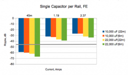
I have heard about a few people trying larger power supply capacitors (C101, C201) and hearing sound quality improvements. That got me to wondering if it made sense. Since we are flirting with a noise floor in the -120 to -130 dB range, it is possible that power supply ripple could be adding to the noise. The LM3886 datasheet specifies PSRR at 85 dB minimum and 105 to 120 typical, depending on source voltages. Using 85 dB as the worst case, the ripple coming into the LM3886 would need to be -45 dB or lower to be below -130 dB.
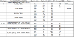
I pulled up the Duncan PSU Designer II program and played with some numbers. I used the specs from an Antek 2224 toroidal transformer (24V, 200 VA) and I picked three current sinks to better understand the performance range. For the bottom, I used 45mA which is basically no signal and represents the quietest passages. Using Mauro's 45W into 8 Ohms, I used the 2.37A required for that spec as full power. Of course, most music isn't full power, so I picked about half (1.19A) to represent “normal” music.
For reservoir caps, I chose 10,000 uF from the BOM and 22,000 uF as a natural size about double the standard size.
ESR of a cap is important for two reasons. It has a minor effect on ripple, but it also affects how quickly a cap can react to a transient requirement from the amp. The Vishay base cap in the BOM has a ESR of 22 mOhms. The alternate premium cap (Nichicon LKG) doesn't spec ESR, but I am estimating it at 19 mOhms from the tan delta information. The Mundorf is the expensive option, although far more reasonable than it was 5 years ago. Mundorf doesn't currently publish the ESR spec, but I have an old datasheet from 2012 that uses 6 mOhms for our size.
I ran simulations of the Vishay and Mundorf caps in both sizes. I also ran the Nichicon, but it wasn't very different from the Vishay in this simulation. From the graph, you can see that it isn't easy getting to -45 dB, but it may be OK as long as you reach that level at the lowest current level, that is, a quiet passage in the music.
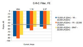
I also ran some combinations using a C-R-C filter. Of course, the resistor in the filter will reduce rail voltage at higher current levels. To compensate for this, these simulations are run using the Antek 2225 (25V, 200 VA). I would have preferred to go up to 26 V, but the standard steps at Antek are 24, 25, and 28V. Using this transformer, I was able to keep rail voltage within ½ volt of the current system, even at full power. Actually, at the mid current flow (1.19A), rail voltage is a little higher than the current system. As you can see, using a C-R-C filter, it is possible to meet the -45 dB target at all power levels. Also note, that I did this using the lower cost Vishay cap. That may have some negative effects due to it's higher ESR on rail voltage transients, so it may turn out useful to have a premium cap closest to the rails.
Now, you say this all very interesting, but how can you do a CRC filter on the existing boards? Actually, it is possible. Just build a small proto board with the diodes, first capacitor, and resistor. Then solder the output of the proto board into the diode holes that connect directly to the rails with the second capacitor mounted in the normal place on the board. I like the idea of having the second cap on the board and a short path to the LM3886.
This kind of separate board offers some interesting options. For example, you can make a low ESR cap out of paralleling several higher ESR caps. Since their resistance is in parallel, the combined caps ESR combines like parallel resistors. 3 of the Vishay 10,000 uF caps would have 30,000 uF and an ESR of 7mOhms.
Another alternative would be to change the board design to accept a CRC filter, but that would mean a pretty large increase in size.
Jac
Let me start with the usual caveat. I am often wrong. Please feel free to correct what I am writing or comment.
I have heard about a few people trying larger power supply capacitors (C101, C201) and hearing sound quality improvements. That got me to wondering if it made sense. Since we are flirting with a noise floor in the -120 to -130 dB range, it is possible that power supply ripple could be adding to the noise. The LM3886 datasheet specifies PSRR at 85 dB minimum and 105 to 120 typical, depending on source voltages. Using 85 dB as the worst case, the ripple coming into the LM3886 would need to be -45 dB or lower to be below -130 dB.
I pulled up the Duncan PSU Designer II program and played with some numbers. I used the specs from an Antek 2224 toroidal transformer (24V, 200 VA) and I picked three current sinks to better understand the performance range. For the bottom, I used 45mA which is basically no signal and represents the quietest passages. Using Mauro's 45W into 8 Ohms, I used the 2.37A required for that spec as full power. Of course, most music isn't full power, so I picked about half (1.19A) to represent “normal” music.
For reservoir caps, I chose 10,000 uF from the BOM and 22,000 uF as a natural size about double the standard size.
ESR of a cap is important for two reasons. It has a minor effect on ripple, but it also affects how quickly a cap can react to a transient requirement from the amp. The Vishay base cap in the BOM has a ESR of 22 mOhms. The alternate premium cap (Nichicon LKG) doesn't spec ESR, but I am estimating it at 19 mOhms from the tan delta information. The Mundorf is the expensive option, although far more reasonable than it was 5 years ago. Mundorf doesn't currently publish the ESR spec, but I have an old datasheet from 2012 that uses 6 mOhms for our size.
I ran simulations of the Vishay and Mundorf caps in both sizes. I also ran the Nichicon, but it wasn't very different from the Vishay in this simulation. From the graph, you can see that it isn't easy getting to -45 dB, but it may be OK as long as you reach that level at the lowest current level, that is, a quiet passage in the music.
I also ran some combinations using a C-R-C filter. Of course, the resistor in the filter will reduce rail voltage at higher current levels. To compensate for this, these simulations are run using the Antek 2225 (25V, 200 VA). I would have preferred to go up to 26 V, but the standard steps at Antek are 24, 25, and 28V. Using this transformer, I was able to keep rail voltage within ½ volt of the current system, even at full power. Actually, at the mid current flow (1.19A), rail voltage is a little higher than the current system. As you can see, using a C-R-C filter, it is possible to meet the -45 dB target at all power levels. Also note, that I did this using the lower cost Vishay cap. That may have some negative effects due to it's higher ESR on rail voltage transients, so it may turn out useful to have a premium cap closest to the rails.
Now, you say this all very interesting, but how can you do a CRC filter on the existing boards? Actually, it is possible. Just build a small proto board with the diodes, first capacitor, and resistor. Then solder the output of the proto board into the diode holes that connect directly to the rails with the second capacitor mounted in the normal place on the board. I like the idea of having the second cap on the board and a short path to the LM3886.
This kind of separate board offers some interesting options. For example, you can make a low ESR cap out of paralleling several higher ESR caps. Since their resistance is in parallel, the combined caps ESR combines like parallel resistors. 3 of the Vishay 10,000 uF caps would have 30,000 uF and an ESR of 7mOhms.
Another alternative would be to change the board design to accept a CRC filter, but that would mean a pretty large increase in size.
Jac
Attachments
5
No stability problems using opa827 (if the work is well done). I have near 0 offset.
Using lm318, my_ref can reach 5k usd quality. Using 827 and all mods it reaches 10k IMHO...
Please define the term "well done."
You guys have convinced me that the OPA827 is worth trying. I am not able to comprehend all the changes that need to be made and what precautions need to be taken to assure this swap will result in a stable amp.
Can someone please summarize what parts need to be removed or changed to accomplish replacing LM318? I have already removed C10 and R39 and changed R3 to .33. I have also changed C34 from 15 to 18pf.
I understand that installing the OPA827 allows for C9 to be jumpered or removed. Is there a test to perform before/after that's done? Just check offset at output? Is there any advantage to changing opamps but leaving C9 in place, or is the primary purpose of changing opamps to be able to remove C9?
Peace,
Tom E
Hi Tom,
page 309, post 3085 gives a step by step description of what needs to change.
As for what is meant by well done, you do need most everything clean and well soldered, not a problem for you, and to measure DC and AC at the output with shorted input. Some people have seen an oscillation which shows up as DC and AC at zero input. In most cases, a small COG or mica cap of 4.7 pF soldered across pins 2 and 6 of the opamp have solved that.
Jac
- Home
- Amplifiers
- Chip Amps
- My_Ref Fremen Edition - Build thread and tutorial