Great work George!
I bought a couple of ADA4627s a while back on your recommendation, but haven't so far got round to making the change as I've been very happy with the sound already. Maybe your latest report is the push I need.
Also, I've always found it odd why the input impedance was not balanced, as it'll spoil offset as well as common mode rejection.
In fact, the other point is power supply rejection.
input stage bias currents are 'inclined' to shift with power supplies.
And this shift with changing power supply then introduces a change in the drop on input impedances.
On different input impedances. Because the bias currents change together, so if they see equal impedances the balance is maintained.
But in case of no compensation for these impedances, Voila, here it is your PSRR leaving through the open window..
Last edited:
So, maybe it would be time to sit down and go through carefully the steps needed for this change, to swap out the LM318.
Give me just a moment..
Ciao, George
Give me just a moment..
Ciao, George
Bas, I had been listening for many many years with the LM318.I understand that you have found a better sounding configuration? I find that very hard to believe. I have zero need to update. 😉 I'm kidding of course... But it happens to be the truth as well.
And I can only tell good stories about it. It has an openness, clear detailed presentation with a sense of 'neutrality' that is only recommandable..
But also a certain 'lightness' in the bass was present, which has changed with the new opamps. Also the sensation of depth. and some other aspects.
Probably worth a try..
So, first of all one should have the 'Rev-A' compensation scheme applied, in place.
http://www.diyaudio.com/forums/chip...on-build-thread-tutorial-265.html#post4793708
These consist of:
Change R3 from .47ohm to .33ohm (uhm, the most 'painful, costly change..)
Remove C10 (33pF)
Remove R39 (470K)
See attach..
Then, for the eventual opamp change the only step left is to remove - disconnect the compensation scheme for the opamp.
This means to remove C34 (27pF) and /or R43, (22kohm)
I usually leave in place C34 (expensive, better not touch) and remove, or just turn 90degree R43, in it's place
With this move one conserved all the bits necessary to an eventual re-install later. Obviously conserve the LM318, too.
Now, for removing the opamp I use Weller or Metcal heated tweezers.
I know I know.. Chipquick is a good solution too..
In case of the ADA4627 / OPA627 / or eventually the OPA1641 this is all.
In case of problems of spurious oscillations (we can discuss the effects) one should install an extra 3.3pF directly across the pins 2 and 6 of the opamp.
Do not install by default, was never needed, except for one occasion, this is why I mention.
The original compensation capacitor, C32(150pF) can be left in place. (whew, all our precious styroflex parts..)
We are done.
Except for usual oversights.. Dario?
Ok: should add: after replacing the new opamp, please visually inspect, re-inspect and again, control that all leads are soldered firmly, and conduction is established.
In case of missing this, costly consequences are lurking in the back..
Always turn on first without anything connected, and wait for the usual, sweet click of the protection relays. All!!
Ciao, George
Attachments

Last edited:
Ah, I forgot the final pass.
After having listened to the system with the opamp changed, here comes the final, joyful move: place a short wire across C9.. 🙂
Obviously, do not beleive / trust not even a half word, and test and test every step carefully. Measure the output offset voltage directly across the output connectors.
Before connecting any speakers!
Also, be sure that your input cap, C13 is in place and functional!!
Any DC leaking through to the input will be amplified ~30 times!!
In case of the precision fet amps, (OPA627, higher grade of ADA4627) not more than a couple of millivolts are permitted at the output
With the OPA1641 should control yet, but would expect not more than a dozen mV also there.
Ciao, George
Last edited:
I've run out of chip quick, so will have to order some. i'I'm also intending to bias the ADA4627s into class A. I've got some current regulator diodes that will do the trick.
So, first of all one should have the 'Rev-A' compensation scheme applied, in place.
Then, for the eventual opamp change the only step left is to remove - disconnect the compensation scheme for the opamp.
Except for usual oversights.. Dario?
Ciao, George
Very interesting. Unless I'm missing something, this could be applied to the FE 1.2 and older boards as well. I've always loved the sound of the OPA627. It might be worth a try on my old boards.
Jac
Spartacus - I'm looking forward to Your opinion.
Class A.. I think it stays in class A, even with the LM318, full power, in this topology. (again, a point to Mauro..)
Let's see, max output from the chip is ~ +-12V peak (14V power supplies)
The load is ~resistive, 47K. Max output current is ~ 1/5 th mA, 250uA.
How much do you think the output stage is biased?
7mA is the total supply current. For the ADA4627, too.
Jac: yes, it can be applied the same, absolutely.
Ciao! George
Ciao George.
I really don't know what sort of bias most opamps use - I'e never seen this info in a datasheet.
My most recent experience biasing an opamp into class A was an OPA827 in the output stage of a DAC. It was driving a pretty high load, even including feedback R, to at most 2Vrms. Very high feedback, very low distortion. Yet it clearly made an improvement, smoothing out the treble. I doubt it was to do with crossover artifacts, my suspicion is that it's to do with thermal behaviour, but that's just speculation.
Dan
But also a certain 'lightness' in the bass was present, which has changed with the new opamps. Also the sensation of depth. and some other aspects.
Wow, I would have never said so... in my setup (probably room modes have a role) there's a LOT of bass...
Except for usual oversights.. Dario?
I don't know... didn't find the time yet to try...I've buyed all bits, though.
Bulk metal foils
They're not as good as nude Z-Foils but better than RN55, for some values those are a bargain:
For R13:
1x Z201 100K00 0.01% Vishay Z-Foil Series Metal Foil Resistors Y1453100K000T0L | eBay
For R10:
1x RNC90Y 392R00 FR Vishay RNC90 Series Metal Foil Resistors Y0089392R000FR0L | eBay
For R7:
1x RNC90Y 12K000 BR Vishay RNC90 Series Metal Foil Resistors Y008912K0000BR0L
Pay attention that Z201 are shipped randonly between Z201 and Z201T (ROHS), ask in advance same code resistors.
Another bargain for R37, R12, R13 (not as good as Z201 or RNC90 but still foil resistors):
0.1% 5ppm 0.5W Very High Precision Vishay SFERNICE Foil resistor values 2R - 3K3 | eBay
http://www.ebay.com/itm/0-1-5ppm-0-...s-100K-/142274715625?var=&hash=item66c147ea03
If budget allows for R12 I would buy a naked Vishay.
Last edited:
Can you hear it?
https://drive.google.com/open?id=0B-qKRBuaKtzYcTRwZk1GTUEyQ0E
Last year I've recorded a small part of an italian song with various caps in C9, C9 shorted and the original file.
Since room modes comes in it's not as easy as live to hear differences but they're still there, IMHO.
I'm curious to see if others hear them as well.
Dear Dan,
As far as I remember, for example for the AD797 500 uA output stage bias is mentioned.
Then, when applied as a line driver stage, even if the load is light, there are some factors:
1; I would not use hundreds of kohm-s in the feedback, interacts with stray input / trace resistances and could cause undesired phase shifts in the feedback, not a good news.
2; At high frequencies, already starting from higher kHz-s, like 10kHz, the interconnect cable reactance (I suppose couple of 100 pF, for a meter of cable) can enter the dozen kohm range.
3; 2Vrms is 6Vpp.
So, at 10kHz, as a load one has: feedback, cable reactance, and even some load, all in parallel.
I can imagine that an output bias of 500uA is not enough.
But in the myref there is one well defined resistive load, 47kOhm, and an AD797 would stay in class A for all cases.
Anyway, I don't want to stop You, far from me, try it.
One precaution: by biasing the output stage higher, You raise the gm of it.
This could have an effect on the open loop gain, and so could change the loop gain stability criteria in the composite amplifier.
So, my suggestion would be: try it without biasing, first.
Then at a later stage, when You already got familiar with the setup, it's stability, it would be interesting also to see it with higher output stage bias.
Ciao, George
Ciao George.
I really don't know what sort of bias most opamps use - I'e never seen this info in a datasheet.
My most recent experience biasing an opamp into class A was an OPA827 in the output stage of a DAC. It was driving a pretty high load, even including feedback R, to at most 2Vrms. Very high feedback, very low distortion. Yet it clearly made an improvement, smoothing out the treble. I doubt it was to do with crossover artifacts, my suspicion is that it's to do with thermal behaviour, but that's just speculation.
Dan
Same here.Wow, I would have never said so... in my setup (probably room modes have a role) there's a LOT of bass...
Dan,
If You already have the OPA827, you could try that, too.
It needs a change, the main compensation should be changed from 150pF to 100pF.
I continue to like it in my setup. We even had the occasion to make an almost perfect, one to one comparison of two EVO-s, equipped equally full with double current pump configuration, Mundorfssses and Zfoilssses in the important places. (and Susumus in all the rest) (whoops, >200euro only in extra modded parts, in both amps..)
One had ADA4627 implanted while mine had the usual OPA827.
The result, for me but we were quite in concordance, that they were more similar sounding at this point than different..
Still, if decision should be made.. hm, now that was a moment for me being shaken in my faith.. and fidelity to the OPA827..
Ciao! G
Last edited:
Wow, I would have never said so... in my setup (probably room modes have a role) there's a LOT of bass...
I would like to be clear: we are talking about finesses, shifts in balance.
The LM318 works definitely very good, too. And it's not the only component which modifies the sound. In my personal experience C9 especially can change it. Like the Nichicon Gold which was for a while also official BOM suggestion, was driving it to the very much warm side.
But in my EVO's and in case of the Black Gate PK in the FE I have always appreciated much the dry, quick, controlled & neutral character of the amp.
The new substitutes, specifically these fet opamps seem to bring more warmth, more full presentation. Without giving up control, seemingly.
Ciao, George
Bulk metal foils
Dario, thanks a lot, another pearl of suggestion. Will try - costs can escape very quick...!
Dario, thanks a lot, another pearl of suggestion. Will try - costs can escape very quick...!
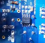
saga of opamps in FE
We have a new partecipant here.. Had been always very curious.
Only tests have been done for now, and the pic had been made before vital compensations applied.
(side note: This guy requires, though, that servo - feedback cap should get back in place..)
We have a new partecipant here.. Had been always very curious.
Only tests have been done for now, and the pic had been made before vital compensations applied.
(side note: This guy requires, though, that servo - feedback cap should get back in place..)
Attachments
I would like to clarify, again, my intention with these measurements.
The principal intention is purely technical, and first of all: stability.
I always start with simulations, explore methods of the possible compensations, do a loop gain and transient analysis. I wish to do loop gain analysis some time in practice, too. Until then, the first prectical test is the transient analysis with the scope, hunting down the faintest still visible oscillations, if present.
Then I learned slowly that also spectral analysis can be a great help: a circuit even if partially unstable, with slightest hints for oscillation -- never will be able to produce such a low distortion spectra that we are getting used to see. It's the intermodulation, mixing down, plus shifting biases, and thermal effects which at the end result in a brutally deformed distortion spectra even with low levels of spurious oscillations.
Then, these measurements, with an objective possibility to make direct comparisons between different partecipants, show the slight/ not so slight !Technical! differences between configurations.
But the final word is always the listening: no way it is intended from my part to substitute that.
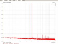
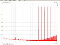
So, with all this put forward, here are the diagrams with the AD797.
First, the usual 1kHz test tone. Then the multitone test, which at one shot returns a lot of interesting aspects. All this in the test modul with external lab power supply.
The principal intention is purely technical, and first of all: stability.
I always start with simulations, explore methods of the possible compensations, do a loop gain and transient analysis. I wish to do loop gain analysis some time in practice, too. Until then, the first prectical test is the transient analysis with the scope, hunting down the faintest still visible oscillations, if present.
Then I learned slowly that also spectral analysis can be a great help: a circuit even if partially unstable, with slightest hints for oscillation -- never will be able to produce such a low distortion spectra that we are getting used to see. It's the intermodulation, mixing down, plus shifting biases, and thermal effects which at the end result in a brutally deformed distortion spectra even with low levels of spurious oscillations.
Then, these measurements, with an objective possibility to make direct comparisons between different partecipants, show the slight/ not so slight !Technical! differences between configurations.
But the final word is always the listening: no way it is intended from my part to substitute that.
So, with all this put forward, here are the diagrams with the AD797.
First, the usual 1kHz test tone. Then the multitone test, which at one shot returns a lot of interesting aspects. All this in the test modul with external lab power supply.
Attachments
Last edited:
- Home
- Amplifiers
- Chip Amps
- My_Ref Fremen Edition - Build thread and tutorial