I suppose that hot glue doesn't adhere very well, but I always thought that hot glue would be a good damping material is I could figure out the correct way.
Dario,
Are your big caps the snap-in kind or the ones with the sticky foam pad? I had hoped that the sticky foam pad would have helped in this situation, but perhaps not.
Jac
Dario,
Are your big caps the snap-in kind or the ones with the sticky foam pad? I had hoped that the sticky foam pad would have helped in this situation, but perhaps not.
Jac
Not all ceramics are created equal... Y5V dielectric is very microphonic, X7R much less and NP0/C0G pretty nothing.The resulting voltages produced can cause appreciable amounts of noise, especially when a ceramic capacitor is used for noise bypassing.
Not so thin... it's 2 mm thick and, while it resonates a bit the effect on big caps is one order of magnitude bigger.I suspect the pcb as well. Its thin and under mechanical stress. So it will have all sorts of sympathetic vibrations. These will not only result in microphonics in the mounted devices but also possibly in the traces which of course have resistance, capacitance and inductance.
Some extreme cross-over builders do it regularly but I think it's not appplicable here, epoxy will interfere with heat dissipation.If you're satisfied with component choice you might consider dipping the amp in resin/epoxy. Thick chassis may help.
This is pretty common in high end commercial gear and a good idea.It might also be helpful to add a metal sheet beneath the pcb on the mounting screws/bolts.
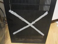
I was also thinking about bracing the internal and adding more screws.
An externally hosted image should be here but it was not working when we last tested it.
(Pic from [AV-Com / puschpull] Sony SCD-555ES)
Notice the extensive bracing and the thick copper base under transformers on the Sony SCD555-ES
Also using gaskets between junctions it's a possibility.
Perhaps add a mounting hole between C102 and C202. Seems that they're not used by anyone. I do like having the pads there in case you want to tap into the regulated supply.
More scews to hold down the pcb should increase the resonant frequency of the board and a thicker board would do the same. You can order boards 5mm thick.
Adding a mounting hole at the center it's a good idea, I'll add it to next revision.
I think just having the cover on the enclosure reduces air borne vibration.
I think too that the cover reduces internal airborne vibration, at least by some amount.
In reality IMHO it's the contrary, they are far mire rigidly bonded to the PCB than TH parts.Although SMD allows shorter signal paths and chips contain microscopic paths, the devices themselves are so much smaller that they are more prone to vibration.
Dario, good idea to damp the caps.
...
I never thought of the big caps.
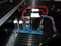
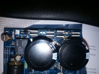
I've simply touched every surface hunting resonance, when I've touched the big caps... wow!
BTW, to sense it by touch I've had to use a very high volume, at disconfortable level.
Probably at lower volume the effect is much lower.
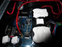
I've attached some pics more.
I've also added a small piece of rubber between big caps, another improvement.
I suppose that hot glue doesn't adhere very well, but I always thought that hot glue would be a good damping material is I could figure out the correct way.
Yes, hot glue works pretty well, I use it on my cross-overs
Are your big caps the snap-in kind or the ones with the sticky foam pad? I had hoped that the sticky foam pad would have helped in this situation, but perhaps not.
They're the foam pads ones but I never glued them to allow reuse.
Attachments
I prefer silicone window sealer as a glue.
Compared to hot melt, it holds stronger, it is more resistance to peel, and it is softer and thus less likely to vibrate and may damp other vibrations better.
I would not cover the exposed metal in case it interferes with heat dissipation.
I actually glue that exposed face to the chassis base plate, thus using the coolest part of the chassis to help cool the capacitors. This also leaves the leads available for connecting by hardwiring and as test points to check voltages and ripple via a scope probe.
Andrew,
For us "show me" types. Have you a picture to illustrate the last half of your post#2183.
" Exposed metal/ heat dissipation". What exposed metal are you referring to.???
"Glue the exposed face". The exposed face of what????
Thanks for the help
For us "show me" types. Have you a picture to illustrate the last half of your post#2183.
" Exposed metal/ heat dissipation". What exposed metal are you referring to.???
"Glue the exposed face". The exposed face of what????
Thanks for the help
heya!
quick one, where can I get the latest PCB for the myref fremen edition?
Cheers!
Schlumpfpeter
quick one, where can I get the latest PCB for the myref fremen edition?
Cheers!
Schlumpfpeter
Hi everyone,
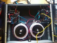
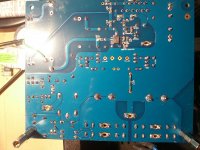
I'm back with a new, troubled FE build. I assembled the boards a while ago, cleaned them thoroughly afterwards and on the first power-up, I was ecstatic to see them both power up as they should, relays clicking simultaneously and all. However, when I attached a speaker to the right channel, with shorted inputs, I noticed that there was a faint but distinctly noticeable 100hz (at least that's what I think it is) buzz present that isn't there on either my previous build or the corresponding left channel, which is working perfectly. I've already tried cleaning it a few more times and I've also replaced D1 and D2, to no avail. The channel plays sound fine, it's just that the buzz is always there as well. The 14 rails are at -14.71 for the negative side and 14.40 (a bit low, no?) for the positive side - the working left channel has 14.65 and 14.5 respectively. Any ideas what might be causing the buzzing?
I'm back with a new, troubled FE build. I assembled the boards a while ago, cleaned them thoroughly afterwards and on the first power-up, I was ecstatic to see them both power up as they should, relays clicking simultaneously and all. However, when I attached a speaker to the right channel, with shorted inputs, I noticed that there was a faint but distinctly noticeable 100hz (at least that's what I think it is) buzz present that isn't there on either my previous build or the corresponding left channel, which is working perfectly. I've already tried cleaning it a few more times and I've also replaced D1 and D2, to no avail. The channel plays sound fine, it's just that the buzz is always there as well. The 14 rails are at -14.71 for the negative side and 14.40 (a bit low, no?) for the positive side - the working left channel has 14.65 and 14.5 respectively. Any ideas what might be causing the buzzing?
Attachments
Last edited:
Try twisting your input signal wires.. Looks like they are parallel and heat shrunk together..
That isn't the issue - I get the buzz even with the input shorted right on the board with the little jumper in the picture.Try twisting your input signal wires.. Looks like they are parallel and heat shrunk together..
Attachments
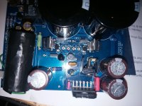
The input of right chanel is too close to Transformer,tray too move board away of transformer and see the result.
The input of right chanel is too close to Transformer,tray too move board away of transformer and see the result.
You were right - turning the transformer so it stands on the side fixes the buzz! Now the only problem will be finding another, more distant spot for the transformers such that the layout in the case is still symmetrical...
Thanks a lot for the help, I'll try out some different mounting positions and report back!
Your transformes are shielded?
Sent from my iPad using Tapatalk
Yes, but I suspect the shields are pretty useless as they're made from copper foil (at least I think they are - I couldn't imagine antek using anything else, considering their aggressive pricing) and connecting them to the amp's ground has no effect on the buzzing. I'd need to get some mu-metal to really make an impact on the transformers' EM radiation.
One other question. What is the green wire that appears to run from the board edge of C13 to somewhere under the board? If that has signal or signal return in it, it might be the antennae that is picking up the transformer noise. Perhaps shorter somehow?
Jac
Jac
One other question. What is the green wire that appears to run from the board edge of C13 to somewhere under the board? If that has signal or signal return in it, it might be the antennae that is picking up the transformer noise. Perhaps shorter somehow?
Jac
No, the problem was definitely the transformer placement on the right channel, I moved it a bit and the buzzing disappeared. I think I'll have to mount the right transformer between the two boards to avoid the noise.
The green wire is for grounding the metal casing of the input cap - it can pick up some noise when it's not grounded.
The green wire is for grounding the metal casing of the input cap - it can pick up some noise when it's not grounded.
Understood. By the way, what is C13? Is that the Vishay 735P under there?
One thought on the transformer location. I have had the transformer about 50 mm from the FE board without noise. Since these things don't need much heat sink, it would probably be possible to put both boards on one heatsink and the transformers on the other side. That might get you more space and not require the mu metal shield.
Just a thought.
Jac
I think I'll have to mount the right transformer between the two boards to avoid the noise.
I'm happy that you solved. 🙂
You're using the same case that I'm using, today I would have bought a different one like the Slimline 2U.
The Pesante Dissipante is way overkill regarding heatsinking and space is a bit scarce for a dual mono build.
The green wire is for grounding the metal casing of the input cap - it can pick up some noise when it's not grounded.
I would use one of the signal ground pads on the PCB for that.
You're using the same case that I'm using, today I would have bought a different one like the Slimline 2U.
Looking at your photo (post #2166) and butizzle's, it clearly shows the size comparison between the R-core and torroid transformers. Wow.
rigorous twisting of all pairs of transformer wires, both mains and secondaries may reduce the buzz in the affected channel.Any ideas what might be causing the buzzing?
The electrostatic shield between the primary and the secondary is an interference screen that takes predominantly HF to chassis.Yes, but I suspect the shields are pretty useless as they're made from copper foil (at least I think they are - I couldn't imagine antek using anything else, considering their aggressive pricing) and connecting them to the amp's ground has no effect on the buzzing. I'd need to get some mu-metal to really make an impact on the transformers' EM radiation.
It does NOT benefit being of ferrous material. Copper is probably best, Aluminium possibly gets close.
Looking at your photo (post #2166) and butizzle's, it clearly shows the size comparison between the R-core and torroid transformers. Wow.
I think you should consider their power ratings before comparing sizes.
- Home
- Amplifiers
- Chip Amps
- My_Ref Fremen Edition - Build thread and tutorial