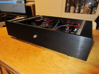
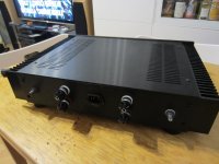
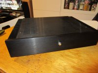
My Ref in Chinese cases
These sound pretty good! Thanks Mr. CF. I do find that they are wonderful on FLAC and unfortunately they are pretty harsh with regular MP3 files. My coworker heard the difference in sound right away. So I explained the difference between audio sources rather than showing off my new mono blocks but these things happen!
Has anybody else ordered these cases from China? They have a particular smell - it isn't bad but distinct. Does anyone know what it is?
I haven't used those cases, but it does seem that they use different chemical formulas in China. Hopefully, the paint or whatever will cure and stop smelling.
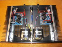
Very nice build. Just curious, what resistor did you use for R3? In the photo it is a big, black round resistor.
Very nice build. Just curious, what resistor did you use for R3? In the photo it is a big, black round resistor.
They are the Vishay Dale resistors: wire wound. I rechecked my BOM and I got them in 6.5 Watt but now Mouser does not have them. They still have the 5 watts but I wanted to be safe. I even double checked the photo - sure enough, the resistors have 6.5 W printed on them.
These amps are not very forgiving in regards to the source material. You think that I should have used a Caddock? I'm sort of loath to mess with them because they sound amazing at low to regular volumes. I have some sealed foster 120's with a solid state subwoofer with a P labs passive frequency splitter in the input cable to the amps.
These amps are not very forgiving in regards to the source material. You think that I should have used a Caddock? I'm sort of loath to mess with them because they sound amazing at low to regular volumes. I have some sealed foster 120's with a solid state subwoofer with a P labs passive frequency splitter in the input cable to the amps.
These amps are not very forgiving in regards to the source material. You think that I should have used a Caddock? I'm sort of loath to mess with them because they sound amazing at low to regular volumes.
The Fremen Edition is pretty transparent so not so perfect source, cables, and whatever before them will be trown in your face...
BTW I think your problem it's with the component selection, you obviously didn't follow completely the BOM.
Experiment with different parts it's a good thing and could lead to new, better choices but I always suggest to start from the BOM and then change, so we all share a common reference.
Why do you have different caps for LM3886 positive and negative decoupling?
One of them seems a Nichicon Fine Gold, bad choice there, a sure source of harshness.
I would replace them with Panasonic FM, Elna RJH or NCC LZX.
Regarding the Vishay output reistors, you could try to reverse them, maybe you mounted them in the worst sounding direction.
Smoothing caps seem Nichicon KS, also subpar, I've already tried them with Rev.C.
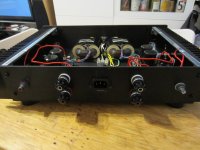
Finished my build... finally
Jac, maybe you'll be happy now... 😀
Jac, maybe you'll be happy now... 😀
Attachments

Dario,
Quality build, as we would expect from you.
Try putting some damping material on the floor of the enclosure, especially around the PCB standoffs toward the center where it is not supported.
I have recently tried Nichicon KZ Muse caps at C9 (with small value bypass at C21) in my old MyRefC's, and they're really not bad. They provide an evenly rich tone in the midrange and decent high freq detail without brightness. They do NOT equal the inner detail of BG's. I am running a pair of Fostex FF165 full-range drivers in back horn enclosures I just built. The MyRef allows for all the depth and articulation of images and smooth tonality that a tube amp could provide, with no noise or heat. Vocals and small ensembles are especially realistic, but the poor little full-rangers cannot quite replicate a full orchestra. I might try significantly reducing the size of the input cap, the notorious C13, to form a first order filter at 50 - 60 Hz to reduce the bass input. The Fostex can't go that low anyway, and it only contributes to excess excursion and distortion. Sometimes you gotta work with what you have.
ICA,
It is difficult to tear into an amp that is working fine, but it probably would help the sound if you match that pair of smoothing caps. Also, I believe the Caddock at R3 is far superior to WW resistors. In fact, I believe a Caddock is superior to any WW in almost any circuit.
Peace,
Tom E
Last edited:
Quality build, as we would expect from you.
Try putting some damping material on the floor of the enclosure, especially around the PCB standoffs toward the center where it is not supported.
Thanks, Tom 🙂
In reality it's not completely finished, I've yet to mount a relay based switch for power on/off and also the PCBs are going to be replaced with a new improved version which will be in the next GB.
Experiment with damping is one of my next goals.
I have recently tried Nichicon KZ Muse caps at C9 (with small value bypass at C21) in my old MyRefC's, and they're really not bad. They provide an evenly rich tone in the midrange and decent high freq detail without brightness. They do NOT equal the inner detail of BG's.
I do agree, they're not bad at all but, timbre-wise they seems too 'full' and miss the detail level of BGs or Silmics II (black ones).
The FKP2 bypass present in last batches of boards should help, though.
I believe the Caddock at R3 is far superior to the Mills. In fact, I believe a Caddock is superior to a Mills in any circuit.
Absolutely.
Jac, maybe you'll be happy now... 😀
Dario, It's beautiful.
I should never tease you about this. My first build for my main system is still on the board. My preamp is on a board too. What is that, 3 years now?
Just curious. What is the blue tube around the mains power wires in the middle of the amp? Is that electro-magnetic shield, vibration damping?
Jac
Thanks, Jac 🙂Dario, It's beautiful.
Why? It's been fun 😉I should never tease you about this. My first build for my main system is still on the board. My preamp is on a board too. What is that, 3 years now?
Yes, I think I've bought the chassis 2 or 3 years ago...
It's just a small piece of a shielded power cable (Furutech FP-3TS20)Just curious. What is the blue tube around the mains power wires in the middle of the amp? Is that electro-magnetic shield, vibration damping?
Is that electro-magnetic shield, vibration damping?
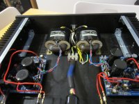
Today I did some tests with damping and discovered that the thick power cable somewhat dampens the back panel... It seems that no damping is needed there.
Space between boards seem to need some, though.
I've dampened the top panel, a small improvement.
What seem to need damping are the caps... Particularly C101 and C201 and to a lesser extent C2 and C4.
The improvement is interesting.
Did you damp the PCB or the caps themselves? I have often considered applying some sort of damping or stiffening to the center of the PCB. It's pretty big and unsupported in the center, right where some of the most sensitive components are located. Any vibration there is likely to add distortion. Those big caps might be "dancing" to the music.
Please tell us more about the "interesting" improvements. I have always noticed a better focus of details, sometimes making highs clearer while simultaneously reducing brightness. Too much damping, however, seems to deaden the sound, moving it back to inside the speakers.
Some of your speaker leads are long and unsupported. Unless the gauge is very heavy, these might benefit from a bit of support or damping. Cotton sleeve? Teflon tubing? Maybe even a sliver of wood taped tightly to them.
Peace,
Tom E
Last edited:
Did you damp the PCB or the caps themselves?
The caps. I've put a bit of 'Blu Tack' over them.
I have often considered applying some sort of damping or stiffening to the center of the PCB.
...
Those big caps might be "dancing" to the music.
I think the problem are the caps themselves, testing by touching the PCB does not resonate, while the caps do, particularly the big ones.
Please tell us more about the "interesting" improvements. I have always noticed a better focus of details, sometimes making highs clearer while simultaneously reducing brightness.
Same thing... focus, blacker background.
The effect is quite obvious and bigger than case dampening one.
Some of your speaker leads are long and unsupported. Unless the gauge is very heavy, these might benefit from a bit of support or damping.
I didn't test them, they're thick solidcore OCC wires.
LT app note an83 page 12 or 13 talks about caps microphonics. Shows output voltage developed by tapping on cap with a pencil.
" Some ceramic capacitors have a piezoelectric response. A piezoelectric device generates voltage across its terminals due to mechanical stress, similar to the way a piezoelectric accelerometer or microphone works. For a ceramic capacitor the stress can be induced by vibrations in the system or thermal transients.
The resulting voltages produced can cause appreciable amounts of noise, especially when a ceramic capacitor is used for noise bypassing. A ceramic capacitor produced Figure␣ B4’s trace in response to light tapping from a pencil. Similar vibration induced behavior can masquerade as increased output voltage noise."
Apparently the foil resistors are supposed to have less microphonics than others.
http://www.vishaypg.com/doc?63244
I know you few guys believe in microphonics but I'm just posting these few sources for the benefit of others.
http://www.vishaypg.com/doc?63244
I know you few guys believe in microphonics but I'm just posting these few sources for the benefit of others.
I suspect the pcb as well. Its thin and under mechanical stress. So it will have all sorts of sympathetic vibrations. These will not only result in microphonics in the mounted devices but also possibly in the traces which of course have resistance, capacitance and inductance. More scews to hold down the pcb should increase the resonant frequency of the board and a thicker board would do the same. You can order boards 5mm thick. If you're satisfied with component choice you might consider dipping the amp in resin/epoxy. Thick chassis may help.
I searched google for pcb trace microphonics and found this thread:
http://www.edaboard.com/thread5789.html
Notice that these folks think high dielectric increases microphonics. If you dont read that article here is an easy to implement snippet:
" To avoid the mechanical effect I've been using epoxy to glue the big parts as tantalum caps, choque bypass, etc... to the pcb. Also any wire should be glued using some epoxy. If lumped coil is used as part of the oscillator's resonator, it should be enclosed in some (plastic) package and this should also be glued."
Last edited:
Good stuff, Uriah. Microphonics of ceramic caps is well documented, and one more good reason to not use them in signal path. The rest of it is uncharted territory. Glue or encapsulation seems a bit drastic, but I guess that's an ultimate solution!
Perhaps add a mounting hole between C102 and C202. Seems that they're not used by anyone. I do like having the pads there in case you want to tap into the regulated supply.
I think just having the cover on the enclosure reduces air borne vibration. It could be due to shielding or merely sighted bias, but I always think mine sound better when covered.
Although SMD allows shorter signal paths and chips contain microscopic paths, the devices themselves are so much smaller that they are more prone to vibration.
Long, unsupported straight wires need damping, as well. I try to put an arc in mine and keep them short.
Dario, good idea to damp the caps. On the old boards when large C9 😀 would not fit down against the PCB, I put a very small bit of foam underneath it before soldering. If C13 was off the board, it was strapped to a piece of foam against the bottom of the enclosure. I never thought of the big caps.
Peace,
Tom E
- Home
- Amplifiers
- Chip Amps
- My_Ref Fremen Edition - Build thread and tutorial