Dario hello, I was hoping for your intervention ...
I realized just now of the presence of indications of the tension at the bottom of the card.
I can detect only 1.26 volts then I do not understand where to put the tester for 35 volt and 116 volt.
I realized just now of the presence of indications of the tension at the bottom of the card.
I can detect only 1.26 volts then I do not understand where to put the tester for 35 volt and 116 volt.
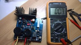
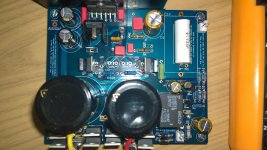
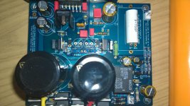
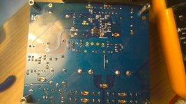
Pics
hello,
here are the pictures. However I also have doubts about how use the tester: I put it in AC or DC?
hello,
here are the pictures. However I also have doubts about how use the tester: I put it in AC or DC?
Attachments
However I also have doubts about how use the tester: I put it in AC or DC?
DC
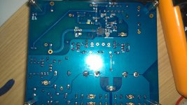
SMD resistors R10 and R13 are missing?
No, he is using the trough-hole counterparts
My mistake.
Don't feel bad, I thought it was a good observation as I missed the through holes also...
Good evening everyone and thanks for the support. Proceeding with the measurements I note 1,261 and 1,257 ( correct is 1,25). Between -35 and +35 points I 67.8 Between -14.6 and +14.6 i have 1,81
Between -14 and +14 i have 0.636.
I noticed that LM3886 not very hot (despite the small heat sink) while the two LM317 heat up a lot (I can not keep my finger on) I hope I have correctly detected the measure.
I hope I have correctly detected the measures, I performed with inputs and outputs disconnected and not shorted. I hope for your help
Ivan
hi
I've re-done the measures with the tester by inserting a tip of GND and one on the various points, here is the result:
where should I have + 14.6V instead 1,05V
where should I have -14,6V instead 0,835V
where should I have -35V instead -34,2V
where should I instead have + 35V + 34,2V
Look a your help
Solved... or almost
Hi square, Having read a bit of theory, pages and pages of posts and old books (at least to avoid stupid questions or trivial) last night I debugged the PCB. Since the problem was "close to the LM3886" I checked carefully in that area and so I saw the blunder: The BC639 traded places with the BC640.
After a difficult repair provider and to take measurements:
OUT / OUT_GND = 10.9 mV
OUT / OUT_GND = 10.9 mV (input shorted)
+ 35V / PGND = + 34,2V
-35V / PGND = + 34,2V
1,25V=1,261V
1,25V=1,257V
+14V=+13,67V
-14V=13,43V
-14,6V=14,1V
+14.6 V = ....... I missed is the tip of the tester and has short-circuited l 'LM317
The relay has clicked and voltages from +14 14.6 and fell to 70mV, while the branch neg. is was ok.
I think the diode is burned in fact with the tester does not give me continuity in no way. Later we will keep the replacement and we'll see how it goes'. Greetings Ivan
Hi Ivan,
good job, from the pics we will never discovered BC639 and BC640 were swapped. 🙂
It's a pity for the short.
The 34,2V measures are fine.
The values don't have to be perfect, some tolerance is normal.
I would focus on the shorted LM317 first.
Is the VREF (1,25V) good?
IMHO It's normal that you can't measure continuity on the zener, I've just tried on some spare zeners and diodes just for the sake of, no continuity in both directions unless they're polarized. 😉
non ho risolto...
Hello, as Dario always right. I replaced the diode but has not changed anything. Then I replaced the 'LM317 but again I have not solved. The 1.25V are ok, the BC639 voltage is 0V on all three pins. He could be the culprit? Got to do something the relay? Thanks
Hello, as Dario always right. I replaced the diode but has not changed anything. Then I replaced the 'LM317 but again I have not solved. The 1.25V are ok, the BC639 voltage is 0V on all three pins. He could be the culprit? Got to do something the relay? Thanks
the BC639 voltage is 0V on all three pins. He could be the culprit? Got to do something the relay?
You absolutely have to replace the BC639 then... you should read some voltages on its pins.
The relay can be bypassed for test connecting speaker - to PGND, no need to check it and BTW it will hardly be interested.
Thanks,
I'm waiting For the componente For the replacement.
Your help is necessary.
Thanks
Ivan
I'm waiting For the componente For the replacement.
Your help is necessary.
Thanks
Ivan
I am going to review that stated to become.the open input will result in quite a lot of noise but only a small increase in the hum component of the noise. You can use an AC voltmeter to measure the change before after shorting the input.
The open input may change the DC voltage at the output. It depends on whether the capacitor leaks or not.
Does this version of myref have a DC blocking cap?
There is a significant increase in both noise and in hum when the input is open.
maybe it works
Hello,
last night I received the transistors BC639-16 and BC640-16 and I immediately replaced the burned (BC640-16), now the situation is this:
OUT / OUT_GND = 8.2 mV
OUT / OUT_GND = 8.2 mV (input shorted)
+ 35V / PGND = + 34,4V
1,25V=1,261V
+14V=+13,67V
-14,6V=14,1V
-35V / PGND = - 34,4V
1,25V=1,261V
-14V=-14,1V
-14.6 V =-14,70
I have some doubts:
the voltage difference between branch positve is negative is the fact that BC639 is the BOM of Mouser while BC640 is purchased from a local store? (pictured second PCB I'm populating where you see the transistor BC purchased in the local shop).
It 's normal I note that the same output voltage of 8.2 mV with both the open input is short-circuited with the input?
And 'normal for LM317 warm enough to not be touched with a finger?
greetings
Ivan
Attachments

Mmh... from the pic both seems different... they should be the -16 version...
In practice any BC639 and BC640 (or BD139/BD140, better the -16 version) will work, simply the -16 versions have more HFE and thus the shunt present a lower impedance.
The +13,67 voltage is on the low side but you should have no problems.
In practice any BC639 and BC640 (or BD139/BD140, better the -16 version) will work, simply the -16 versions have more HFE and thus the shunt present a lower impedance.
The +13,67 voltage is on the low side but you should have no problems.
Hello,
I am preparing my BOM and I have a question about parts R39 and R43. In the Dario's BOM, the power rating for these parts is 1/4 W but the Mouser part numbers give parts with a power rating at 1/8W.
Is it not too low?
Same question for R12, R37, R13, R104 and R204.
Thank you for you help.
🙂
I am preparing my BOM and I have a question about parts R39 and R43. In the Dario's BOM, the power rating for these parts is 1/4 W but the Mouser part numbers give parts with a power rating at 1/8W.
Is it not too low?
Same question for R12, R37, R13, R104 and R204.
Thank you for you help.
🙂
Ignore the rating on the BOM for smd parts.
I'ts not updated for SMD parts and still have the TH values (sometimes overrated).
BTW if you're making your own BOM be aware that it's possible you'll obtain lower perceived performance.
I suggest you to post here (or PM me, as you like) about the parts you're going to use so that I can tell you if they've been already tryed.
- Home
- Amplifiers
- Chip Amps
- My_Ref Fremen Edition - Build thread and tutorial