It would have been better to attach images directly...
BTW
Why are you using so small C101, C201?
Any impression on sound?
BTW
Why are you using so small C101, C201?
Any impression on sound?
It would have been better to attach images directly...
BTW
Why are you using so small C101, C201?
Any impression on sound?
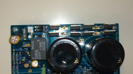
I have to replace C101 C102. I am doing a test with mp3 and the sound seems very good. More details later.
@oloppolo,
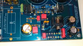
Looks good. I'm glad you are replacing the power supply caps. I think you will hear some improvement. Can you tell us what you are using at C13? It looks a little like one of the old ERO caps, but different.
For years, we have given Dario a hard time about the heat sink that he uses for testing🙂. It is this strange old plate, with cut-outs and holes. I'm sure that it works fine, but it doesn't look very much like a heat sink. Happily, Dario has a good sense of humor about this.
I hope you have a good sense of humor too, because your heat sink looks funny too ;-). I'm happy that your build is going well and look forward to your comments on the sound.
Jac
C13 is ERO MKP 1839. The heatsink is 0.900 Kg of aluminium, it stays cool. This is for testing. I'm looking for a box to complete the project. First impressions are very good.
: D
: D
Some pics of my first realization
hello great forum,
with great difficulty and very little time I have finished my first pcb (missing only LM3886).
Hope I have not made too many mistakes, but I have no illusions ... the possibility that the LED lights up, the relay "click" and the tension is correct it is really far away ...
greetings
ivan
Attachments

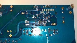
Seems a nice job.
I would reflow some joints, thought...
Don't even try to power it on before mounting J1... It should be have mounted as one of the first parts... Before the big smoothing caps, now you will have to solder it from the bottom of the boards.
I would reflow some joints, thought...
Don't even try to power it on before mounting J1... It should be have mounted as one of the first parts... Before the big smoothing caps, now you will have to solder it from the bottom of the boards.
...oooops
..... that's the first mistake ...
Do you think I have to re-weld it all?
Thanks
Ivan
..... that's the first mistake ...
Do you think I have to re-weld it all?
Thanks
Ivan
thanks for the solidarity,
unfortunately the time to devote to the project is very little, also (oloppolo will understand) I am a '' natural born nchiappusu "...
but with your help I can finish the project.
thanks
unfortunately the time to devote to the project is very little, also (oloppolo will understand) I am a '' natural born nchiappusu "...
but with your help I can finish the project.
thanks
Hello,
before welding LM3886 I can do some checking (measure the voltage at some point) to see if everything is ok?
thanks
before welding LM3886 I can do some checking (measure the voltage at some point) to see if everything is ok?
thanks
Help me
hello,
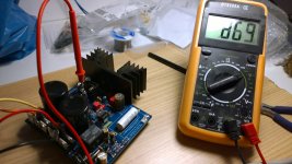
after welding the missing jumper, the LM3886, the C13 I prepared the test lamp and finally I connected the transformer to the board. I took the courage and turned on ...
Unbelievable !!!
1) Test lamp passed.
2) Led on
3) I hear the relays "click"
I can not believe, it works !!!
My joy is short-lived, however, the time to take the tester and perform the voltage measurement of out-gnd_out: 0.889 volts. It should be less than 20 mV, where I went wrong?
Help!
Ivan
hello,
after welding the missing jumper, the LM3886, the C13 I prepared the test lamp and finally I connected the transformer to the board. I took the courage and turned on ...
Unbelievable !!!
1) Test lamp passed.
2) Led on
3) I hear the relays "click"
I can not believe, it works !!!
My joy is short-lived, however, the time to take the tester and perform the voltage measurement of out-gnd_out: 0.889 volts. It should be less than 20 mV, where I went wrong?
Help!
Ivan
Attachments

Have you shorted input signal to input ground?
You must use a larger heatsink. You'll kill the amp with that tiny thing. Make sure lm3886 is isolated from the heatsink if the chip is the metal tab version.
You must use a larger heatsink. You'll kill the amp with that tiny thing. Make sure lm3886 is isolated from the heatsink if the chip is the metal tab version.
that tiny heatsink on the chipamp will allow operation from low voltage supply.
expect +-20Vdc to be OK when NOT delivering output current, (from about 15Vac transformer).
Try using a 16r to 22r dummy load and drive some output current while you monitor chipamp temperature.
expect +-20Vdc to be OK when NOT delivering output current, (from about 15Vac transformer).
Try using a 16r to 22r dummy load and drive some output current while you monitor chipamp temperature.
Hello,
the small sink is temporary, just to take the test, also not very hot (just warm).
LM3886 has not the metal tab.
I did not understand whether the measurement should be done with the input shorted or not. The tutorial I understand that must be made with a two measurements open input (<20 mV) and an input with short (<10 mV).
thanks
the open input will result in quite a lot of noise but only a small increase in the hum component of the noise. You can use an AC voltmeter to measure the change before after shorting the input.
The open input may change the DC voltage at the output. It depends on whether the capacitor leaks or not.
Does this version of myref have a DC blocking cap?
The open input may change the DC voltage at the output. It depends on whether the capacitor leaks or not.
Does this version of myref have a DC blocking cap?
Thanks for the answers, I'm sorry but my level is really low and I can not follow you technically, also do not understand English well. If you could tell me step by step what to do would be grateful
Hi Ivan,
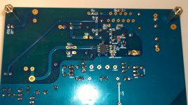
did you measure voltages on measuring points on the bottom of the PCB?
They do match?
Also...
Did you clean accurately the PCB after soldering?
Did you double check that every component is the right value in the right place?
Please post magnified pics so that we can help you checking.
did you measure voltages on measuring points on the bottom of the PCB?
They do match?
Also...
Did you clean accurately the PCB after soldering?
Did you double check that every component is the right value in the right place?
Please post magnified pics so that we can help you checking.
- Home
- Amplifiers
- Chip Amps
- My_Ref Fremen Edition - Build thread and tutorial