At last my amp is singing 🙂
(...)
A few pictures of my build...
🙂
Really nice and clean build.
Waiting for comments on sound... 😉
There is a barely audible buzz (sorry, i don't know if that's the right word for 'ronzio') but i can only hear it with my ear a few inches from tweeter and no music playing.
It seems to disappear if i use as source an ipod, so it could be a ground loop issue; i should investigate this, but i like so much what comes out of the speakers that I think I will listen to music instead 😉
It seems to disappear if i use as source an ipod, so it could be a ground loop issue; i should investigate this, but i like so much what comes out of the speakers that I think I will listen to music instead 😉
Unless you use double insulated transformers with no mains earth connection you will most probably always get some noise, if it's not noticeable from your listening position I wouldn't bother about it. Many commercial amps also produce some hum/buzz which is audible with your ear close to the speaker. I also found it depends on what I use for a source. Enjoy your creation, the FE is a stunning amp in my opinion.
Enjoy your creation, the FE is a stunning amp in my opinion.
That's exactly what i'm doing 🙂
By the way i agree with you, the FE is a stunning amp 🙂
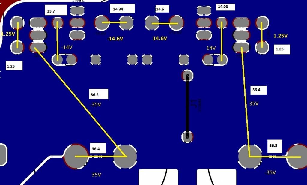
Finally got around to replacing the suspected components and there has been some progress. Can someone give me an opinion on the voltages below, especially the fact that i am getting 14.3 rather than 14.6.
Much appreciated guys. Will post some pics soon.

Much appreciated guys. Will post some pics soon.
Can someone give me an opinion on the voltages below, especially the fact that i am getting 14.3 rather than 14.6.
It shouldn't be a problem, IMHO.
The zener has been replaced?
There is a barely audible buzz (sorry, i don't know if that's the right word for 'ronzio') but i can only hear it with my ear a few inches from tweeter and no music playing.
Benedetto, I can't see any link between chassis and safety ground.
I can see that transformers shields are tied together to one of the bolts.
I would connect them to safety ground, as all panels.
Grounding side panels (the ones you're using as heatsinks) could possibly fix your (slight) hum problem.
Thank you Dario, maybe it was not clear from previous pictures, but the transformers shields are tied together and with the safety ground cable with the ground bolt.
Could you please check this picture and give me your advice?
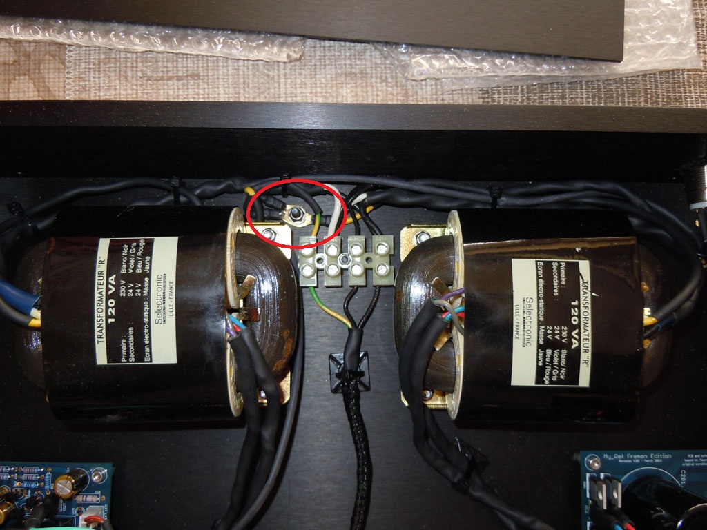
About the side panels i have scratched the contact point with the base panel, but did not check if the contact was good 🙂
Thanks Oleg, looking forward to some photos when you get it installed.😉
It shouldn't be a problem, IMHO.
The zener has been replaced?
Yeah Its been replaced. I Just went and replaced that entire row of components.
Yeah Its been replaced. I Just went and replaced that entire row of components.
Fine. 🙂
It you already checked the passives and for solder bridges you should proceed soldering the lm318 and lm3886 then.
sigh taking of the lm318 i took 1 pad completely off and the other half off.
im screwed arent i.

Atleast 1 channel and buffalo dac i just built work..... but **** what an incredibly stupid and demoralizing thing to happen.
im screwed arent i.

Atleast 1 channel and buffalo dac i just built work..... but **** what an incredibly stupid and demoralizing thing to happen.
Last edited:
What does Pin5 do in the lm318?
If it does nothing, then it does not matter that the pad is lost.
Where a Pad is lost to a Pin that is required you can add a hardwired connection.
A strand of bare copper stripped from a stranded cable will do.
0.1mm, 0.15mm & 0.2mm diameter strands are common in the smaller stranded cables.
If the wardwire strand needs insulation because it could become misplaced and touch another part of the circuit, then a short length of insulation stripped from a CAT5 cable will do. It has a bore of ~0.5mm and has fairly thin insulation, so can be made to fit into quite small spaces.
Last edited:
If i'm not wrong that pad is not connected (check Dario's tutorial at the end of page 6), so if the half ripped one is still usable you should be able to use the board.
sigh taking of the lm318 i took 1 pad completely off and the other half off.
Pin 1 is unused so, as Andrew already pointed out, it's not a problem.
The other pin (half off) is connected on theother side,so it should not be problem too.
Simply, when you solder the new lm318 in place and apply solder to that pad use gently the iron to flatten it a bit.
Last edited:
LM318 is written that way up to show pins1 to 4 below the name and pins 5 to 8 above the name.
Is that the way you laid out the opamp?
Pin1 should be below the L of LM318.
Pin8 should be above the L of LM318.
Is that the way you laid out the opamp?
Pin1 should be below the L of LM318.
Pin8 should be above the L of LM318.
Pin 1 is unused so, as Andrew already pointed out, it's not a problem.
The other pin (half off) is connected on theother side,so it should not be problem too.
Simply, when you solder the new lm318 in place and apply solder to that pad use gently the iron to flatten it a bit.
Just soldered the lm318 and it is a bit bumpy but all other pins look connected though. hopefully tonight i will know if im ok or not.
thanks to everyone also
LM318 is written that way up to show pins1 to 4 below the name and pins 5 to 8 above the name.
Is that the way you laid out the opamp?
Pin1 should be below the L of LM318.
Pin8 should be above the L of LM318.
I laid it out so that the circle marked on the board is beneath the marking on the lm318
Use the continuity function (with the buzzer/alarm) to check from pin to the next component.
will do
- Home
- Amplifiers
- Chip Amps
- My_Ref Fremen Edition - Build thread and tutorial