I hope in a comment by Dario or other certainly much more experienced than me.
In the meantime, I ordered a new set of active components from Mouser.
This weekend I'll be able to investigate with the help of spare parts.
Sergio
In the meantime, I ordered a new set of active components from Mouser.
This weekend I'll be able to investigate with the help of spare parts.
Sergio
Higher voltages shouldn't hurt until they're under 18-19V but there's something wrong with the PS that should be fixed.
Sergio, did you measure voltage directly on zeners?
Sergio, did you measure voltage directly on zeners?
Do you mean 1N5244B, I think.
Measures are:
positive rail : 13.85V. At the control point 14.32V
negative rail : 14.44V. At the control point -18.18V.
I'm using a ICE mod. 5400 tester
Sergio
Measures are:
positive rail : 13.85V. At the control point 14.32V
negative rail : 14.44V. At the control point -18.18V.
I'm using a ICE mod. 5400 tester
Sergio
Last edited:
Do you mean 1N5244B, I think.
Exactly 🙂
negative rail : 14.44V. At the control point -18.18V.
So you have correct Vref at the LM317, correct voltage at the zener and wrong value after the transistor... my bet is on the BC640.
Today I replaced the BC640 but I did not get the desired result, so I replaced the LM317 and the voltage on the negative rail is still -18V.
I stopped here.
The amplifier is fantastic and sounds great. Voltages are in the range I think that is better now to listen my favorite music. 😉
In any case I would fix this out of standard negative voltage if anyone wants to help me I give you more information.
Due to the randomness with which I chose the active components for two modules and for the positive and negative parts, made me suspect only the BC640, but as the replacement did not change anything I have to assume that it is probably some component works incorrectly.
I measured this voltages:
positive rail:
lm317 36.13V(in) 15.68V(adj) 14.43V(out)
mp915 1.25V
zener 14.47V
bc639 14.48V
negative rail:
lm317 -36.13V(out) -34.88V(adj) -18.01V(in)
mp915 1.25V
zener 14.44V
bc640 -18.01V
The toroidal transformer is a TALEMA 230V 2x25V 3.15A.
AC1 e AC2 voltages are both 27V.
Have you connected the capacitors C102 and C202 in the circuit? The first time I mounted the breadboard, I measured ,with the tester, wrong output voltages (higher than I expected) .Touching with the fingers the wires of the tester, the voltages changed. Probably there were oscillations on the output voltages. By connecting two capacitors 10micro, 50V on the output (C102 and C202) I got output voltages stable and fixed = +/- 14 volt stable. Could be this the problem you have.
The amplifier plays very well also in the bread-board form, with long messy wires .
The amplifier plays very well also in the bread-board form, with long messy wires .
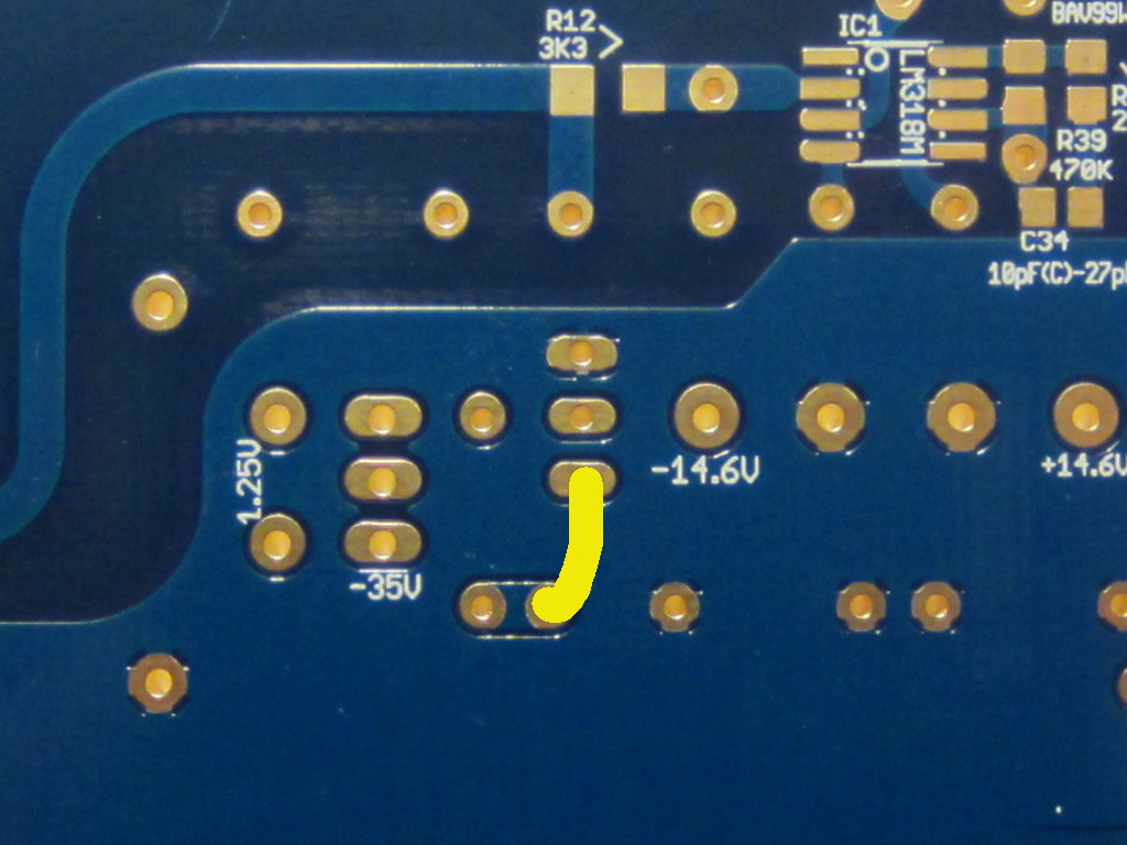
PCB 1.10 problem (easy fix)
I can't understand how but while generating the Gerbers I've sent to manifacturing a tiny bit (1.5mm) of a track of the negative regulator have been chopped in the Eagle project.
It can be easily fixed with a very short jumper wire (solid core preferred, a wire trimmed from a capacitor or a resistor will be perfect):
I've checked again the gerbers, comparing also with previous' GBs ones, and I didn't find further problems.
The fixed PCB will work perfectly and I expect no impact on performance.
I'm really sorry for that... if someone from the 5th GB can't live with it please PM me.
Attachments

Dario,
No to worry. This is DIY. Stuff happens. And happily it is easy to fix. I once had a similar issue with a commercially sold kit/pcb. That amp is still working 30 years later.
Just curious, is this the reason for Sergio's power supply voltage error? I just fired up 4 V1.02 boards built with components were probably bought to the same specs as Sergio's and the voltages were all fine.
Jac
No to worry. This is DIY. Stuff happens. And happily it is easy to fix. I once had a similar issue with a commercially sold kit/pcb. That amp is still working 30 years later.
Thanks Jac 🙂
Just curious, is this the reason for Sergio's power supply voltage error?
Yes, the base of BC640 is not connected to the output on 1.10 boards, the jumper restore the connection.
I just fired up 4 V1.02 boards built with components were probably bought to the same specs as Sergio's and the voltages were all fine.
I'm using too 1.02 boards and all voltages are fine, the 1.10 are the only ones affected by this problem.
Attachments
Fixed !!
Thanks for the help, Dario!
You're welcome 🙂
So now the output is -14.6V?
Sorry for this problem.
Dario, I take the opportunity to say that Mauro and You have developed an excellent project. While I’m writing this post, I'm listening to Eric Clapton optimally amplified by My_Ref FE.
From the electronic point of view, do you know if the oscillations I had on the voltages +/- 14Volt happened to some other DIYer? The question is: the capacitors C102 and C202, foreseen in the diagram on the +/-14V, have been used? I must connect them and all works fine, otherwise I have oscillations on the +/-14V.
Thanks, Luigi
Dario, I take the opportunity to say that Mauro and You have developed an excellent project.
Thanks 🙂
From the electronic point of view, do you know if the oscillations I had on the voltages +/- 14Volt happened to some other DIYer?
None I'm aware of.
The question is: the capacitors C102 and C202, foreseen in the diagram on the +/-14V, have been used? I must connect them and all works fine, otherwise I have oscillations on the +/-14V.
C102 and C202 are not needed, in fact later versions of PCBs retain the position but with clear indication to be left unpopulated.
It's pretty weird that oscillation... did you do some troubleshooting on it?
[It's pretty weird that oscillation... did you do some troubleshooting on it?]
I have not performed any troubleshooting. I made a breadboard and as soon as i connected the LM317, the zener, the resistor between the output and the Adj terminals, the transistor, I measured the output voltage: +18V… +16V … +12V, depending by the movements of my hand around the tester cables. With an analog tester i saw the index of the instrument moving up and down.
I put a capacitor (10 microfarad) on the output voltage and magically I read the correct value: 14V stable end fixed.
Now the amplifier is working very well, I connected a capacitor also on the negative 14v. I don’t want to touch it since it’s working fine, but I will make a new breadbord to investigate…
Thank you, Luigi
I made a breadboard and as soon as i connected the LM317, the zener, the resistor between the output and the Adj terminals, the transistor, I measured the output voltage: +18V… +16V … +12V, depending by the movements of my hand around the tester cables.
Hi Luigi,
Did your oscillation only occur on the breadboard, or did you find the same on the FE board? Just curious. It would be easy to have something different between pcb and breadboard that would cause oscillation.
By the way, I agree, if it sounds good now, no need to change it.
Just for background, I have 6 FE boards working, none with the C102/C202 caps and no oscillation seen.
Jac
HI Jac,
Since on the breadbord the oscillations stopped with a simple capacitor, i connected the capacitors on the printed populated board without any more questions....
The printed circuit is not a FE board, but a my elaboration: i preferred to have only one separated power supply for both the channels....
But as soon as possible I will try to understand better the things with a new bredaboard and mainly with the switched on oscilloscope.
Regards, Luigi
Then it's normal you need output caps on the regulator... On the FE they can be omitted since the distance between regulator and opamp is really short and C7 is all it's needed.
- Home
- Amplifiers
- Chip Amps
- My_Ref Fremen Edition - Build thread and tutorial