I forgot that was what you were doing.I had a bipolar in the cascode, but that makes bootstrapping of the cascode
clumsy. Even if the source of the input FET has only 200 mOhm to GND,
that does not mean that the FET runs in pure CS. By action of the 40 dB
feedback divider, the FET sees a replica of its AC input at the source, just
as if it was a follower.
So, when I connect the gate of the cascode to the source (and not GND),
I get the bootstrapping for free; no level shifter or gate driver is required.
I have been doing that with the Supertex parts (now Microchip so harder to get details) for years. It has worked really well with no obvious down side except possibly needing a little added C or RC at the input for stability. You can also get the full voltage range of the Mostfet (up to 400V I think) which can enable some design options that are otherwise very difficult or impossible.
I think that C is simply needed to bond the FET gate somewhat to GND, even
when no low impedance is connected to the input. The feed back needs some
reference point. The 66Meg bias R works close to DC, but at RF the gate and
drain would float around, from the feedback's point of view.
The Microchip stuff is still at Mouser, (maybe Digi-Key?), including data sheets.
That's where I got mine.
The other source of depletion FETs would be Infineon. They even sort their
transistors by pinch-off voltage, but they only guarantee the same selection group
on a reel. You cannot order "2 Volts". Maybe with some social engineering.
BSS159N, BSP149, BSP135, BSP129 & friends.
cheers, Gerhard
Last edited:
What Id would you want to run your IF3602, and how much Vds should the cascode provide ?
Any additional requirements, such as Cgs or Yfs ?
Patrick
Any additional requirements, such as Cgs or Yfs ?
Patrick
I'd like to break the 100 pV/rtHz, or see how far I get. I'm aware
that more current helps only prop. to the 4th root, but at that level
every small improvement comes with quite some cost, and then
throwing away 20% for not increasing Id leaves a bad feeling.
I also want it repeatable without sorting. That may be impossible
with the IF3601 since at a given Vgs some specimens may be
fully conducting while others still are off.
Bootstrapping away the input capacitance paves the way
to adding more transistors. But it must be stable with any
source impedance. Gate stoppers simply do not exist at
this noise voltage density.
I'd like to break the 100 pV/rtHz, or see how far I get. I'm aware
that more current helps only prop. to the 4th root, but at that level
every small improvement comes with quite some cost, and then
throwing away 20% for not increasing Id leaves a bad feeling.
Have you thought of LN2 cooling, all the testers use that you also get the dry nitrogen purge for free? The peltier systems for amateur astrophotography don't seem to go low enough since their noise problem is more exponential in nature.
Just a note: generally FETs are having an optimum temperature for noise between 100K-150K. Below 100K the curve starts to rise quite steep and at 77K might reach noise levels well above the value at room temperature.
Last edited:
Just a note: generally FETs are having an optimum temperature for noise between 100K-150K. Below 100K the curve starts to rise quite steep and at 77K might reach noise levels well above the value at room temperature.
Not 100% true for some exotic processes (pHEMT's work at 4K as LNA's). The LN2 chambers are thermostatically controlled anyway, obviously limited by LN2 temp. FET's at least don't freeze out but in any case the low frequency and high frequency noise behavior diverge (sometimes dramatically) and everything gets complicated.
I studied a dozen or so commercial FET op-amps for .1 to 10Hz noise down to freeze out of the bi-polars. The results were all over the place.
Yes, I should have been more precise: I was meaning jfet-s. Other technologies do not show this problem, but in general they produce worse 1/f noise knee. Especially pHEMT's are much worse at low frequencies.
Just a note: generally FETs are having an optimum temperature for noise between 100K-150K. Below 100K the curve starts to rise quite steep and at 77K might reach noise levels well above the value at room temperature.
I've been out of the field of device physics for some time -- what causes the increase in noise as you lower the temperature? I'm assuming we're talking Si JFETs rather than other materials, e.g. SiGe/SiC.
And, yeah, freeze out of minority carrier based transistors will happen much sooner than FETs.
It seems to be a good study on this topic.
http://pessina.mib.infn.it/Biblio/Biblio_Articoli/SPIE Volume N.5470 p 486 496 2004.pdf
Ciao, George
http://pessina.mib.infn.it/Biblio/Biblio_Articoli/SPIE Volume N.5470 p 486 496 2004.pdf
Ciao, George
I've been out of the field of device physics for some time -- what causes the increase in noise as you lower the temperature? I'm assuming we're talking Si JFETs rather than other materials, e.g. SiGe/SiC.
And, yeah, freeze out of minority carrier based transistors will happen much sooner than FETs.
GR noise as that paper shows for silicon. The activation energy for the traps is highly temperature dependent and several variables are process dependent. J W Haslett and E J M Kendall have many papers on this topic also. Most commercial IC op-amps have the behavior as that article (our study was for private info and was never published) but there were examples that behaved differently (we never learned why).
Last edited:
Yes, that's the original from which all else has come forth.
Thanks, guys. Had thought about shallow donors, but hadn't thought that cooling would expose shallow donors.
Forget about the Locky_Z.
Patrick
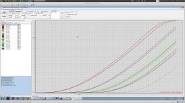
I finally have tried to use the curve tracer over this weekend.
You seem to be right.
Could it be that Locky_Z is really Vroomfondel from my .sig?
Not a single result that seems to make sense, never twice the same answer.
😡
(Really, Vr. is from Douglas Adams' The Hitchhiker's Guide To The Galaxy,
not from my .sig. To me, D.Adams & Terry Pratchett seem to have the
clearest view of all there is in the universe.
Last edited:
For curve tracing FETs, the simplest is to use a 2-channel storage scope, plus a functions generator to drive the gate.
I use 100Hz and adjust the amplitude DC offset to get the range of Id I want.
Current is measured across a sensing resistor (50R S102) at the source.
It is necessary though to have a scope with more than 8 bit resolution.
Mine has 14 bit, and I measure 2x complete cycle with 2000 points.
The data is then fitted by a 6th order polynomial, e.g. in Excel.
Once you have set it up, it is real quick and easy.
Patrick
Oh, my scopes all have only 8 bits, and none has less than 2.2 GHz bandwidth 🙂
But I'm working on a 14 bit digitizer with 1250 MSPS and 2 GHz BW.
But this morning, I continued playing with the Locky-z. With JFETs I had more luck than with the 2N2222.
Still should be taken with a grain of salt, results from 8 IF3602 JFET pairs:
But I'm working on a 14 bit digitizer with 1250 MSPS and 2 GHz BW.
But this morning, I continued playing with the Locky-z. With JFETs I had more luck than with the 2N2222.
Still should be taken with a grain of salt, results from 8 IF3602 JFET pairs:
Attachments
- Home
- Design & Build
- Equipment & Tools
- My version of the G = 1000 low noise measurement amp (for Ikoflexer)