I'm not a school trained EE just an audiophile who builds stuff. So how does one sort out the fake transistors from the real ones? There ought to be a test bench circuit that one could use and apply real world loads to sort out the bad ones before one assembles a project. Apply the top collector to emitter voltage or exceed the collector to emitter breakdown voltage??? This ought to be a simple test circuit that allows measuring beta/hfe to allow matching and also c-b capacitance. Thanks, Ray
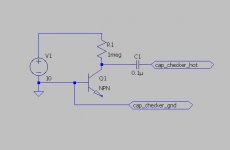
see my previous post. a curve tracer with the ability to detect the second breakdown region (nondestructively) is the best bet. i'll post a B-C capacitance test circuit if you like, it's rather simple.
the circuit shown is for npn transistors. reverse the supply for pnp. the 0.1uf cap is a mylar or other non-electrolytic type.
Attachments
Last edited:
a poly cap like coupling used for tube amps can work ?
the supply has to be exactly 10v ?
if its higher or lower eg a 9v battery, how does it affect measurement ?
the supply has to be exactly 10v ?
if its higher or lower eg a 9v battery, how does it affect measurement ?
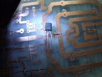
few pics
An externally hosted image should be here but it was not working when we last tested it.
An externally hosted image should be here but it was not working when we last tested it.
An externally hosted image should be here but it was not working when we last tested it.
An externally hosted image should be here but it was not working when we last tested it.
those look like genuine current production...
it must be 10V because that's the condition in the data sheet. if it's 9V the reading will be about 10% higher., since the voltage affects the depletion layer thickness. the B-C junction is acting like a varactor. the bias voltage is to a) establish a repeatable reference point for the test, and b) to move the test voltage far enough away from 0V to keep the capacitance tester from forward biasing the junction, causing faulty readings (because the capacitance gets very nonlinear as you approach conduction)
it must be 10V because that's the condition in the data sheet. if it's 9V the reading will be about 10% higher., since the voltage affects the depletion layer thickness. the B-C junction is acting like a varactor. the bias voltage is to a) establish a repeatable reference point for the test, and b) to move the test voltage far enough away from 0V to keep the capacitance tester from forward biasing the junction, causing faulty readings (because the capacitance gets very nonlinear as you approach conduction)
Query about Toshiba sc5200 transistors
Some time ago I (see post 405) I asked for opinions about whether my Toshiba sc5200s were genuine. The answer seemed to be that they were. More recently I had a bad amplifier driver transistor failure which I am trying to troubleshoot. One possible cause was bad power transistors )the sc5200's I had asked about.
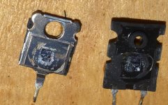
I have split open 2 of them after the failure and to me the internals do look genuine. But I'm hoping someone with more expertise can give me their opinion.
Some time ago I (see post 405) I asked for opinions about whether my Toshiba sc5200s were genuine. The answer seemed to be that they were. More recently I had a bad amplifier driver transistor failure which I am trying to troubleshoot. One possible cause was bad power transistors )the sc5200's I had asked about.
I have split open 2 of them after the failure and to me the internals do look genuine. But I'm hoping someone with more expertise can give me their opinion.
Attachments
Zin,
the legs may be a packaging option.
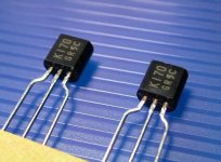
The printing on the face is completely different from my 2sk170 batches.
the legs may be a packaging option.
The printing on the face is completely different from my 2sk170 batches.
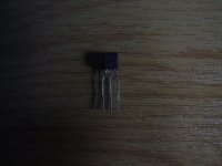
I came across some 2SK170V and 2SJ74BL which have Pins bent in a way which doesn't agree with the datasheet.
Se the attached picture how the pin look like.
would the nice 'red/orange' color on upper legs be a good indicator, and in this case positively pointing at genuine 😕
Zin,
the legs may be a packaging option.
The printing on the face is completely different from my 2sk170 batches.
Thank you for this information.
I'll take some pictures from parts I have in stock, let's see then.
But not sure I can do it this evening.
Zin,
the legs may be a packaging option.
The printing on the face is completely different from my 2sk170 batches.
Zinsula, The printing is like my batch, but the legs I have are straight, a packaging option I assume. These legs in your photo are like the j74's. You should test them anyway.
Pins bent in a way which doesn't agree with the datasheet.
Tino-baby,
not one Toshiba datasheet mentions bent-leg options, but sure can be ordered, plenty examples, try K107, K246, K363, K366.
Gender bender leads likely means late production runs.
Attachments
Yep, sometimes I would like to get back some (in this case, some means quite a lot, unfortunately) years.Tino-baby....
Gender bender, ......hehe.....Gender bender leads likely means late production runs.
Thanks anyway for the information, it is very useful.
DIYers, beware of DIY gene. I bought a pair of 805T tubes from him, one was bad. he told me to return it. return ship was $52. Sent it priority USPS he said he never received the faulty tube. He won't return emails to resolve issue.
Beware fake 2SK170BL
I've just bought a batch of 2SK170BLs from www.dalbani.co.uk
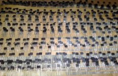
They have proved to be fakes.
I've just bought a batch of 2SK170BLs from www.dalbani.co.uk
They have proved to be fakes.
Why do you think that they are fakes? Have you measured them? And?
Some time ago I (see post 405) I asked for opinions about whether my Toshiba sc5200s were genuine. The answer seemed to be that they were. More recently I had a bad amplifier driver transistor failure which I am trying to troubleshoot. One possible cause was bad power transistors )the sc5200's I had asked about.
I have split open 2 of them after the failure and to me the internals do look genuine. But I'm hoping someone with more expertise can give me their opinion.
big die, looks about right. what is that about 5 or 6mm? that's what it should be, and as your picture shows, no goo on top of the die.
big die, looks about right. what is that about 5 or 6mm? that's what it should be, and as your picture shows, no goo on top of the die.
Thank you for the reassurance unclejed613. I also came to the conclusion that they were ok. I had split open some other similar power transistors which I knew to be genuine and when I compared them to the sc5200s they all looked much the same.
In the future, if I am in any doubt at all about the pedigree of power transistors, then I will buy one or two extra ones, split one open and look inside.
I think sacrificing one device is the most practical way to check. It is cheap insurance because a power transistor which fails and creates an output short circuit can have dreadful consequences to both the amp and speakers.
Why do you think that they are fakes? Have you measured them? And?
DEFINITELY FAKES. Idss measures at 2mA for the badged 2SK170BL.
Idss should be between 6 and 12mA. Even the devices look re-badged. Look at the wiping marks on the face of the devices.
Dalbani were very quick to replace them.
Funny how the whole batch were low Idss whereas a previous order were well within spec.
Attachments
Last edited:
- Home
- Design & Build
- Parts
- My Transistors, original or copy?