Finesse Voltage Regulator Noise!
Hello !
i found this Website:
http://www.wenzel.com/documents/finesse.html
what do you think about the solution ?
Hello !
i found this Website:
http://www.wenzel.com/documents/finesse.html
what do you think about the solution ?
An externally hosted image should be here but it was not working when we last tested it.
An externally hosted image should be here but it was not working when we last tested it.
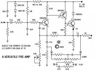
It seems an over complicated design mainly to be used as a RIAA preamp.
If your aim is to test a more sophisticated line amp design I would go with the SL10 which has common mode rejection at the input and no cap on the signal path.
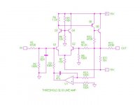
I have redrawn, for clarity, the schematic of the SL10 from Nelson’s site which I reproduce here.
If your aim is to test a more sophisticated line amp design I would go with the SL10 which has common mode rejection at the input and no cap on the signal path.
I have redrawn, for clarity, the schematic of the SL10 from Nelson’s site which I reproduce here.
Attachments
Hi Tony,
thanks for the comment and extra effort to redraw the sl10
to tell the truth, I already built sl10 /i even owned original sl10 for several years/
now i am intrigued by ns10 topology, its more se like
i plan to built russ schematics, an maybe the one i posted, for comparison, i am not interested in riaa, only in line preamp
can you and others comment on the schematics i posted?
anything you would change?
thanks
ed
adason said:
can you and others comment on the schematics i posted?
anything you would change?
thanks
ed
I would change it to NS10
nothing more

NS10 schematics
I have had this for 27 years or so. It is the NS10 schematics. I believe it is correct. I tried to email it to Mr. Nelson Pass first, for a check, but the emails did not go through. But I am so pretty sure it is an original, I dare to post it. Enjoy!
Rolv-Karsten
I have had this for 27 years or so. It is the NS10 schematics. I believe it is correct. I tried to email it to Mr. Nelson Pass first, for a check, but the emails did not go through. But I am so pretty sure it is an original, I dare to post it. Enjoy!
Rolv-Karsten
Attachments
Thanks a lot indeed, Rønningstad🙂 That is a very nice addition to this thread😉NS10 schematics
Steen😎
Yes, thanks. I only had a copy drawn from memory - I don't
know who drew this, but it looks authentic.
know who drew this, but it looks authentic.
Just after I posted the schematics I realised it was on graph paper, so it is probably ME who made this drawing 26 - 27 years ago, but not from memry, mind you! ;-) I cannot remember, an "original copy" migth be around somewhere here, or I was allowed to make a copy in the old way with pencil and paper. I had a colleague who serviced Ampzillas etc, and he also had access to other goodies, like Threshold schematics. (These amps probably never broke ;-)) Anyway, I still believe it is correct, however it is copied from some original. By the way, I seem to remember we had the M1 schematics also in those early days..... (I think some of my friends made NS10 clones way back 1/4 century ago.)
Rolv-Karsten
Rolv-Karsten
tnx from me ,too 😉
do you remember what voltages are in PS of NS10?
or I must say-voltage .....(not plural 😉 )
do you remember what voltages are in PS of NS10?
or I must say-voltage .....(not plural 😉 )
NS10 power supply voltage
Hi, I never knew this, but my vintage Threshold brochure says 24 Volts. 😉 I also think those guys building it used 24 V DC. How the original PSU was implemented I do not know. Maybe NP himself remembers this. BTW the brochure may give a hint.
Regds
Rolv-Karsten
Hi, I never knew this, but my vintage Threshold brochure says 24 Volts. 😉 I also think those guys building it used 24 V DC. How the original PSU was implemented I do not know. Maybe NP himself remembers this. BTW the brochure may give a hint.
Regds
Rolv-Karsten
hehe-it's nice to see tht servo ,not for null but for Vcc/2 purpose.....and nice sink instead resistor in output stage.....
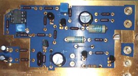
Now the question emerge, are we gonna rebuild the NS10 clone and make it more authentic? The one made allready sounds pretty good but , with the new information that R-K was kind enough to post, why not? I am in😉
Steen😎
Steen😎
steenoe said:Now the question emerge, are we gonna rebuild the NS10 clone and make it more authentic? The one made allready sounds pretty good but , with the new information that R-K was kind enough to post, why not? I am in😉
Steen😎
It has to be authentic.
just later components.
allan

- Status
- Not open for further replies.
- Home
- Amplifiers
- Pass Labs
- My Take on Threshold NS10