Stabist said:hehe - I've realized from where my confusion 🙁 Silly me
Ofcourse - I should be more careful with datasheets where transistor is drawn 3 views(ground plan, side view, ...)
Geee, feel sooooo stupidright now

I always draw notes on paper in my usuall habit-legs to me,face down,if necessary.
hehe-I made mistakes more than once ,before I make that habit
steenoe said:
Stabist, you are not alone on that one😀 Yes the BC's have different pinout than those on Russ's board.
Happy building.
Steen🙂
Hehe - nice to hear I'm not alone in it 😉 😎
Gee ... I've done a p2p placement of components for stereo NS10 circuitry (but not solder it yet) - man - it's small 😎 Must build similar sized PSU too 😎
choky said:
I always draw notes on paper in my usuall habit-legs to me,face down,if necessary.
hehe-I made mistakes more than once ,before I make that habit
hehe - the mistake I made was - I've done notes and sketches of placement of components - from top view (and marked legs) - and then opened Philips's datasheet - where ofcourse legs are marked as looking it from bottom; then opened another datasheet (with 3D drawing of transistor) - and ofcourse now I had "different markings" hehe
hehe ... nice school for next time Are you going for the shunt reg? I hope you are indeed, just to see if it works for somebody else. (I had a little trouble with buzz as you remember if you read the whole threadMust build similar sized PSU too
 ) You can keep a shunt reg pretty small as you can see on the pics I posted earlier. The sound of it is just great🙂
 Steen🙂
steenoe said:
Are you going for the shunt reg? I hope you are indeed, just to see if it works for somebody else. (I had a little trouble with buzz as you remember if you read the whole thread
Steen🙂
lalalalalala........
I don't have buzzzzzzzz
lalalalalala.......


Did you calculate the resistor values for the 431 device? I am also curious how you would connect that device to the negative side.just half
Steen🙂
choky said:
hehe
you can't
Hehe - do you wanna bet
😎 😉steenoe said:
Are you going for the shunt reg? I hope you are indeed, just to see if it works for somebody else. (I had a little trouble with buzz as you remember if you read the whole thread
I'll try it out with shunt reg probably in next version/attempt - because right now what I have at hand is a bunch of LM317/337 ...
Which schematic did you use for your regulator?
choky said:just half
not tried yet
series reg part (left part from dotted line) shared between channels
317 CCS and shunt for each channel on chared pcb (reg+audio)
edit- 50mA per stage
Hmm - as a start I wanted to build similar version as your series reg part (double series regulator) with additional power resistors at the output to have constant load ...
but now - this seems tempty 🙂 (but I'll have to buy some parts ...)
Btw - trimer - if decided not to use it - do I just simply connect emittor of Q1 directly to -V?
Which schematic did you use for your regulator?
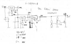
I used this except I didnt use darlingtons (yet) I used BD139/BD140, and didnt use the diodes at the output. I tried with more capacitance also (2200uf's) and some other variations.
http://www.diyaudio.com/forums/showthread.php?postid=794628#post794628
If Choky's doesnt buzz, maybe its my perfboard thats bad😀
I better get some new ones😀
Here is a pic:
http://www.diyaudio.com/forums/showthread.php?postid=785841#post785841
Steen🙂
steenoe said:Did you calculate the resistor values for the 431 device? I am also curious how you would connect that device to the negative side.
Steen🙂
didn't calculated yet resistors
connecting?
like zenner-
exactly the same,just final resistor chaaaaaaaange place


tip for steen:
minus is always minus
plus is always plus
what you'll call ground
that's your choice
if you are good at it
components will agree with your choice
mods!
where's mine "reinventing the wheel" smiley??
Thats the kind of guidance I need allright🙂 I fiddled with the neg rail and the 431 device with no luck😀tip for steen:
Steen🙂
I would like to see a working schematic😉 I did connect the 431 as you say is the obvious way, but but but.......connecting?
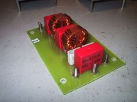
Well, I want to discuss the main supply a little more. I just went through some boxes of (big surprise!!) electronic stuff and found this. Take a look at the pic. Isnt that a mains filter of some sort?
Could I try that in front of the trafo? Ofcourse I could try, I know that😀 But would it be reasonable?? Any chance it would cancel out the darn buzz??🙂
Steen🙂
Attachments
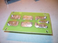
steenoe said:Here is another from the rearside. As you can see on the tracks, it was made for heavy duty🙂 I would appreciate it if someone could tune in on this.
Steen🙂
bingo!
nice one
side with three legs- one is line,middle is ground,other side is neutral (in my country line and neutral are interchangeable,meaning that wall outlets and device plugs are not .....hm...phased-if that is proper word.
other side-with two legs -is output to load ;one line,other neutral
try it,immediately
tomorrow I'll try to fiddle with negative 431 and post
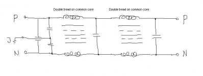
in a meantime ,one example
:
http://www.diyaudio.com/forums/attachment.php?s=&postid=766245&stamp=1131941055
Thanks Choky🙂 I thought this little circuit would come in handy some day😉 I will give it a shot🙂 I just love the simplicity of the shunt reg. Its kind of in the NP-spirit. Sooo the more complicated versions isnt excactly my kind of stuff!try it,immediately
Steen😎
Thanks Analogair🙂 Nice to have validation on this! I can see its a CLC filter of some sort, with the L's having a (presumably) ironcore! Other than that, I know not a thing about how it works??Jep, it's a Mains Filter.
Steen🙂
Edit. Now I see, (I think) You edited while I posted🙂
Well, Choky as "Papa Apass" said I have always something hiding under my sleeve 


The faces are for Isidora, that little sweet girlie of yours🙂
Steen🙂
The faces are for Isidora, that little sweet girlie of yours🙂
Steen🙂
steen
tnx in Isidora's name 😉
if you are in a hurry-you can try this "317 cascode+317CCS+.....) with BD shunt stage instead tl431+mosfet
for my liking,this will be even better
I said -liking,not measuring or listening
tnx in Isidora's name 😉
if you are in a hurry-you can try this "317 cascode+317CCS+.....) with BD shunt stage instead tl431+mosfet
for my liking,this will be even better
I said -liking,not measuring or listening
- Status
- Not open for further replies.
- Home
- Amplifiers
- Pass Labs
- My Take on Threshold NS10