I think you can, just pop them in. This preamp has been tried with several different transistors with good effect.could I just BC549's and BC559's?
I guess you mean C6 in the last schematic. That cap was added in case of instabillity. I dont use any C6. (I havent got a scope to check for anything like that.)Tell me more about C4 (from base to collector of Q1)
If you have an inputcap in the poweramp, you dont need C2. Apassgear said something about the values of C2, in one of the first pages of this thread. I dont think you need to change R10 and R11.I am thinking about leaving out C2 for the time being given input capacitors on my LM3886's. But the input capcitance is only 2.2 uF on the LM3886 amps.
Yep, thats (almost) the one🙂Was your previous pre-amp the one designed by Carlosfm
Steen🙂
my humbleness thinks that A is around 5-6 figure (R1/R2 ?)
I didn't use that C6 jobbie
if you leave output cap out-you can leave out also R10 (buffer resistor) and R11 (cap loader-so you don't have full C2 when you disconnect cables from preamp)
steen-try darlingtons instead BDs
I didn't use that C6 jobbie
if you leave output cap out-you can leave out also R10 (buffer resistor) and R11 (cap loader-so you don't have full C2 when you disconnect cables from preamp)
steen-try darlingtons instead BDs
I will, Choky.steen-try darlingtons instead BDs
I ordered some Darlington pairs together with the TL431's and some other goodies.
I am quite determined to make this shunt reg quiet🙂
Steen🙂
tip from my brother in crime -Oly
instead of series resistor(s) -you can try flying CCS,adjusted to current you need (in our case ,with 35V input) -around 45-50mA
you can make it with 431 or discrete,whatever;
instead of series resistor(s) -you can try flying CCS,adjusted to current you need (in our case ,with 35V input) -around 45-50mA
you can make it with 431 or discrete,whatever;
just tried my BOZ ,still without the case-in same setup as I tried monomia NS10
in same conditions😛ioneer PD8500-monofeed-now BOZ-diy A1-SS Alnico two ways conclusion is that NS10 and nice BOZ are definitelly in same league
BOZ is slightly euphonic -in tube meaning- and NS10 is just brutall.
I like both ways ,under condition that gadgets are in that league that they simply sings.
Master is our good Grand Pa
with lots'a patience
BOZ is slightly euphonic -in tube meaning- and NS10 is just brutall.
chocky
Did you comment about i/o caps in your BOZ? I´d like to upgrade cheap panasonics with some film&foli or PIO. Is it an overkill?
Thanks and keep the good job
JC
JC Fardo said:
chocky
Did you comment about i/o caps in your BOZ? I´d like to upgrade cheap panasonics with some film&foli or PIO. Is it an overkill?
Thanks and keep the good job
JC
your ears will decide-not mine or anybody else's
it's not overkill
Thats a brilliant idea🙂 That ought to take care of everything🙂 Right now I am fiddling with the TL431 version😀 I will not know what to do with my time, when we have solved everything in this thread😀 I better slow down a bit.steen?
Ohhh, I could just enjoy some music comming from this little preamp😉
Steen😎
steen-now,when you almost finnished your F2 iteration  -did you tried anything new with NS10?
I was occupied with some sad familly issues latelly;
in next severall days I'll try to etch few main PCBs and will also try CCS
feeding shunt reg (one flying CCS instead two series resistors)
my friend Oly is in a middle of development of some discrete OP stages with Jfets,in classicall Borbelly-follower style (meaning that Oly is follower,not stage),but-he is making some discrete flying CCS ,along with discrete OP controlled shunt regs;
as I make fun with him-"you make 4 channels of your amplification stage: two for controlling shunts which feeds rest two stages...."
it just sounds silly.....
funny-but thrue- speed is everything in regs,but only when is combined with short paths ,results in singing stage.
Oly is up his throat in CD modifications;this discrete OP is intended to be "cheap" substitute (I say surogat,hehe) for tube output stage for sayed purpose;
we will see what is better -LM based CCS with plain darlington shunt ,or discrete CCS with discrete OP controlled shunt xistor.....
in next few weeks,I hope
if something of this will be good enough-I'll post results and I'll try to make almost universal shunt reg for voltage amplification stages
hehe-probably Oly's reg version will be much better than "mine",so I'll must begg for permition to publish....
-did you tried anything new with NS10?I was occupied with some sad familly issues latelly;
in next severall days I'll try to etch few main PCBs and will also try CCS
feeding shunt reg (one flying CCS instead two series resistors)
my friend Oly is in a middle of development of some discrete OP stages with Jfets,in classicall Borbelly-follower style (meaning that Oly is follower,not stage),but-he is making some discrete flying CCS ,along with discrete OP controlled shunt regs;
as I make fun with him-"you make 4 channels of your amplification stage: two for controlling shunts which feeds rest two stages...."
it just sounds silly.....
funny-but thrue- speed is everything in regs,but only when is combined with short paths ,results in singing stage.
Oly is up his throat in CD modifications;this discrete OP is intended to be "cheap" substitute (I say surogat,hehe) for tube output stage for sayed purpose;
we will see what is better -LM based CCS with plain darlington shunt ,or discrete CCS with discrete OP controlled shunt xistor.....
in next few weeks,I hope
if something of this will be good enough-I'll post results and I'll try to make almost universal shunt reg for voltage amplification stages
hehe-probably Oly's reg version will be much better than "mine",so I'll must begg for permition to publish....
Choky,
Sorry to hear about your sad family issues, hope you recover soon.
I'm not Steen, you know, but it will be nice to see some really good shuntreg, as you say, something that really make the NS10 sing.
Shortly I'll be trying some regs. 😱 😴
😴
Have you tested solo TL431 mated to the NS10?
Happy New Year to all!!!


Sorry to hear about your sad family issues, hope you recover soon.
I'm not Steen, you know, but it will be nice to see some really good shuntreg, as you say, something that really make the NS10 sing.
Shortly I'll be trying some regs. 😱
😴 Have you tested solo TL431 mated to the NS10?
Happy New Year to all!!!
Gain again
Hello team,
I have just built my version of the NS10 using BC549 and BC559. I only am getting a voltage gain of 2 (1V peak to peak on input: 2V peak to peak on output ... measured with a friend's scope.)
That doesn't seem like much to me. I would have guessed a voltage gain of about 2.5 to 3.
Is it the transistors I am using which are responsible for the low gain?
Haven't listened yet. Haven't put on bypass capacitors across supply capacitors yet either. I am just worried that I have done something wrong in the board or soldering.a
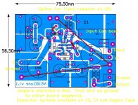
I put the transistors in using those individual little machined gold-plated thingies that you can mount IC's in if you don't want to solder in an IC. Another thing that amazed me was how different the output tracing is with different transistors of the same type ... asymmetrical output about zero volts. Plug in others, and everything is hunky dory! Makes me think that some of the transistors are just shot even when you buy them.
Here is a picture of my first (published) PCB. Be gentle please. I hope there are no errors of wiring which would explaing the low gain.
Hello team,
I have just built my version of the NS10 using BC549 and BC559. I only am getting a voltage gain of 2 (1V peak to peak on input: 2V peak to peak on output ... measured with a friend's scope.)
That doesn't seem like much to me. I would have guessed a voltage gain of about 2.5 to 3.
Is it the transistors I am using which are responsible for the low gain?
Haven't listened yet. Haven't put on bypass capacitors across supply capacitors yet either. I am just worried that I have done something wrong in the board or soldering.a
I put the transistors in using those individual little machined gold-plated thingies that you can mount IC's in if you don't want to solder in an IC. Another thing that amazed me was how different the output tracing is with different transistors of the same type ... asymmetrical output about zero volts. Plug in others, and everything is hunky dory! Makes me think that some of the transistors are just shot even when you buy them.
Here is a picture of my first (published) PCB. Be gentle please. I hope there are no errors of wiring which would explaing the low gain.
Attachments
George,
Nice circuit with all 3 transistors close togather.
I havent gone thru all the circuit but what calls my atention is C4 that should be in parallel with C7 and in your conecction is not, better check that I think.
Nice circuit with all 3 transistors close togather.
I havent gone thru all the circuit but what calls my atention is C4 that should be in parallel with C7 and in your conecction is not, better check that I think.
yup-you're not Steen,but Steen is here (I think) fastest NS cloner ,at least in this thread........apassgear said:Choky,
I'm not Steen, you know, but it will be nice to see some really good shuntreg, as you say, something that really make the NS10 sing.
Shortly I'll be trying some regs. 😱
Have you tested solo TL431 mated to the NS10?
huh, I'm lost in this few NS threads,or I'm not?!
I didn't tested 431 yet,just because I dont have two of them in my drawer-just one ...and I didn't remember to take few (dozens 😉 ) last time when I go in parts shopping
I'll try it soon,I hope;
one thing is important - at least one pair of ears must try all iterations of this shunt regs and then pass xperince to others,for further evaluation
I choose darlington for shunt element just because I have plenty BDXes and I believe that is better to have higher beta device in this place........?
besides all that-from my previous adventures in world of DIY audio electronics,I believe that shunt reg ,when properly constructed ,is superior to any sort of series reg;
this is pretty easy achievable in that current range ,needed for NS10 and even something like BOZ or some other variation
for my habits ,burning anything to 200mA is piece of cake,even in few multiples (bipolar supplys,dual mono config etc)
so-seems that steen have all needed parts already at home......but I presume that he is pretty bussy this days just listening to MUUUUUUUUUUSIC!
what can be better and more important than this-meaning that listening is still more important than constructing gadgets.......
Yep, I am here😀 And still working on the NS10 Megaclone🙂 I am building on the TL431 supply at the moment. Will keep you posted for sure🙂 Yep, a bit busy with family matters right now😉but Steen is here (I think) fastest NS cloner ,at least in this thread........
Happy Newyear, guys😎 😎
Steen🙂
BTW, George, the NS10 I built is far more powerfull than I expected. It drives Zen-amps with ease and very dynamic sound. I didnt check your board, but something must be wrong somewhere in there. Please check it carefully against Russ's layout.
My problems
Hello Apass, Stenoe, and team.
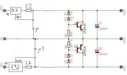
1. I am using the schematic from Post#30 with added power supply caps 6 and 7. That schamatic labels C4 as the little bridging capacitor between the base and collector of Q1. Which schematic is everyone else using????
2. I completely re-drew the board using this schematic (as a check) and all the connections look the same as they did the first time, so I need another plan of action. I can see no solder bridges and all the joints look fine. I will compare connections, at your suggestion, with Russ's board too.
3. Today I plan to change all the transistors again and check they are all working. I have a sneaking suspicion that the ouputted waveform looked the same with and without transistor Q3 in place, which would indicate a major problem!! 😱
4. I've got to get the "right" transistors from somewhere, even some BC550 and 560's might help. But how much measurable difference should having BC549's and BC559's make ... not much?
5. I am not using the ouput capacitor, so I will take up the suggestion in this thread to remove/short out R10 and R11 which are still currently connected and wasting a bit of voltage.
Looking at Lumanauw's first post, it appears that the gain should be 10k/2.2k from the resistors R1 and R2, i.e. 4+. I am not getting that.
Thanks for the advice so far. If I am not careful, I will be putting too much work into this pre-amp, which was just meant to be a stop-gap!! But it is worth persisting given its Nelson Pass pedigree! But it takes George to really stuff a good thing up though ...
Regards,
George.
PS. I have built the power supply using CarlosFM's schematic for his (Re)-searched pre-amp which uses LM317s and LM337 regulators and just boosted the voltage to 24V, which was the "easy part"!
Hello Apass, Stenoe, and team.
1. I am using the schematic from Post#30 with added power supply caps 6 and 7. That schamatic labels C4 as the little bridging capacitor between the base and collector of Q1. Which schematic is everyone else using????
2. I completely re-drew the board using this schematic (as a check) and all the connections look the same as they did the first time, so I need another plan of action. I can see no solder bridges and all the joints look fine. I will compare connections, at your suggestion, with Russ's board too.
3. Today I plan to change all the transistors again and check they are all working. I have a sneaking suspicion that the ouputted waveform looked the same with and without transistor Q3 in place, which would indicate a major problem!! 😱
4. I've got to get the "right" transistors from somewhere, even some BC550 and 560's might help. But how much measurable difference should having BC549's and BC559's make ... not much?
5. I am not using the ouput capacitor, so I will take up the suggestion in this thread to remove/short out R10 and R11 which are still currently connected and wasting a bit of voltage.
Looking at Lumanauw's first post, it appears that the gain should be 10k/2.2k from the resistors R1 and R2, i.e. 4+. I am not getting that.
Thanks for the advice so far. If I am not careful, I will be putting too much work into this pre-amp, which was just meant to be a stop-gap!! But it is worth persisting given its Nelson Pass pedigree! But it takes George to really stuff a good thing up though ...
Regards,
George.
PS. I have built the power supply using CarlosFM's schematic for his (Re)-searched pre-amp which uses LM317s and LM337 regulators and just boosted the voltage to 24V, which was the "easy part"!
George,
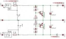
Yes, you have been working with a different Schematic. We are using the one on post 126.
Even though both are the same thing there are some changes on component numbering.
So far it has already been built by Steen with no apparent problems and I'm sure that any problem with yours can be ironed out.
For start, Steen is not using C6 (C4 on the older schem) and I would suggest you leave it out of the circuit for the time being (value will depend on the transistor used).
Q3 is a buffer so no appreciable change will be found on output voltage. Leaving it out will only make a higher output impedance preamp and the feed back schem will be different, something that I would not recommend.
As we all know, different transistors have different pinouts so I would also suggest you make sure you have those connections right. Q1 and Q3 are NPN and Q2 is a PNP.
I think BC560 (B or C but not the A classification) is a good replacement for Q2.
I’ll check which BC will make a good replacement for Q1/Q3 and will also have a closer look to your board.
Happy New Year!!!
- Status
- Not open for further replies.
- Home
- Amplifiers
- Pass Labs
- My Take on Threshold NS10