Thanks hifinutnut, your comments always bring something new to the table.
If you did not see this resonance before and you see it now, it's possible something about the new construction is causing it. I always told you I'll help if you only say when you have a problem. Have you tried disconnecting the preamp and regulator boards? I think you may have a ground routing problem more than interference from neighbouring devices (which is also possible). If you send me your layout and a diagram how it connects to the rest of the system I might be able to help. Now I'm thinking I should have sent you some pcb boards for testing.
A month later, I built 5d with a newly improved layout. It sounded equally awesome but I saw from my scope that there might be a resonance near 1MHz between 500uV to 800uV peak to peak, which was the limit I could see from my scope so I was not sure. My scope is limited to 0.01V per grid, so even 500uV to 800uV peak to peak would only appear to be a thicker line. But a couple of weeks later I found out what had happened. The regulator did not resonate. It never did (with the limit I can observe from my scope). I had a dirty ground which affects measurements, and the scope is not a high-end one. Even when I turned off the preamp / 5d regulator, and put the probe and the ground wire to the preamp ground (earthed) at the same spot I saw exactly the same thing - a resonance near 1MHz between 500uV to 800uV peak to peak! Turning on or off the regulator makes no difference in the line I see in the scope, doesn’t this show that the regulator has no resonance, and if any, would be lower than 500uV that can’t be seen from my scope?
Of course, there is still a puzzle. Why didn’t I see the resonance of 500uV to 800uV peak to peak in my first round measurements while building 5a? Would my neighbor have recently installed some electrical devices that make my house electricity / ground dirtier? In whichever case, it probably has nothing to do with the regulator.
If you did not see this resonance before and you see it now, it's possible something about the new construction is causing it. I always told you I'll help if you only say when you have a problem. Have you tried disconnecting the preamp and regulator boards? I think you may have a ground routing problem more than interference from neighbouring devices (which is also possible). If you send me your layout and a diagram how it connects to the rest of the system I might be able to help. Now I'm thinking I should have sent you some pcb boards for testing.
I would highly recommend using the ISL9R3060P2! And don’t use the garden variety diodes! Theoretically, 5d would give very high line regulation. But I guess that figure comes from modeling, in which case an ideal capacitor (C3) is assumed. But C3 is only an electrolytic capacitor and won’t work very well in high frequencies. So possibly the very high line regulation can only be realized in lower frequencies. The diodes possibly generate a lot of high frequency noise that can not be filtered with C3, so some noise comes through. With ISL9R3060P2, the switching noise is substantially reduced.
Earlier I also mentioned that I was experimenting shunting C3 with a 0.1uF film cap. Eventually, I did not like the sound so it was removed.
Which capacity should be C3?
I have the chance (and will) to buy expensive 470uF polypropylene caps, to be used where is worth. This may be a case 🙂
If you did not see this resonance before and you see it now, it's possible something about the new construction is causing it. I always told you I'll help if you only say when you have a problem. Have you tried disconnecting the preamp and regulator boards? I think you may have a ground routing problem more than interference from neighbouring devices (which is also possible). If you send me your layout and a diagram how it connects to the rest of the system I might be able to help. Now I'm thinking I should have sent you some pcb boards for testing.
Thanks for your offer. I guess I need to do a bit more before I ask for help, as I need to take my own responsibility. There are a number of things I can try to find out the problems, just that I have not had much time in the past a couple of months.
The good news for my DIY is that I finally received my retrenchment letter last Thursday and finished up my work last Friday. Thanks for the economic crisis and senior management's "great vision", that our department (which is profitable and has great potential) was axed and the operation moved to India. That is how yesterday I had the time to get back to the discussion. I have not started looking for work yet, and am giving myself at least a few weeks' break for rest and to finish my hifi project. I am just waiting for some parts to come from UK Farnell, and this time I will move on building things very quickly.
With the line level preamp / XO / EQ I am building, the transformer is screened. To this date I have always earthed any chassis. I am actually thinking about not earthing this particular chassis, just like most commercial CD/DVD players out there. The transformer screen goes to the earth. This should give the quietest ground. I have read all the "safty" warnings. Although I don't have a double insulated transformer, I can't see any reason that the transformer can melt without the fuse blowing first and the house safty switch activated. Shout at me if you think I will kill myself.
Which capacity should be C3?
I have the chance (and will) to buy expensive 470uF polypropylene caps, to be used where is worth. This may be a case 🙂
Telstar,
You can click on Ikoflexer's 5d link and see which C3 in the schematic. Oops, the value is now 220uF.
I guess that even a 4.7uF polypropylene may be bulky enough to pick up enough noise, more than the capacitor tries to remove.
I have a few 220uF Solen polypropylene caps, and they are the size of a dinosour egg. I tried them on my tube preamp power supply. They sounded bad! So I have never used them. They were a waste of money.
A good electrolytic cap (I used Rubycon ZL 470uF / 35V) works well until hundreds of kHz region, beyond human hearing range. However, with power supply rails any ripples above that still impact on the sound. I would use a raw supply without ripples above a few hundred kHz, instead of putting a large MKP in the position of C3.
My change to the soft and fast recovery diodes which improved the sound indicates that very high frequencies still get through my raw supply. Salas has just hinted me that it may be due to the parasitic capacitance of the inductor, and I fully agree. I have more homework to do.
Oh, guys, please don't take the cap values as carved in stone or optimized. They are only an indication that a capacitor in that position improves the performance. The actual value is a trade-off usually.
Edit: hifinutnut, there's a nice article by Bob Pease about noisy ground and what to do about it. You might want to consider that before doing something unsafe.
http://archive.electronicdesign.com/Articles/Index.cfm?ArticleID=21808
Edit: hifinutnut, there's a nice article by Bob Pease about noisy ground and what to do about it. You might want to consider that before doing something unsafe.
http://archive.electronicdesign.com/Articles/Index.cfm?ArticleID=21808
Last edited:
I would hesitete introducing another opamp which requires a very quiet supply itself. Less is more.
I have a couple of RF common mode chokes and I wonder if I could use them and how.
I have a couple of RF common mode chokes and I wonder if I could use them and how.
If I were you I'd make sure it is RF that's spoiling your soup. If indeed it is, do a search on how radio guys get rid of RF on the line. I've found a while ago some nice info about that. Basically you can do wonders sometimes before the RF ever hits your circuit. Ferrite is your friend too.
However, it's my opinion that most often it is ground routing that's giving us trouble.
It's not trivial getting rid of these issues. The measuring probes themselves will bring in noise. As soon as we're talking sub millivolt signals, anything and everything can dirty the waters.
Here's more from Bob Pease.
What's All This Ground Noise Stuff, Anyhow?
And I agree with you about yet another opamp in the circuit 😀
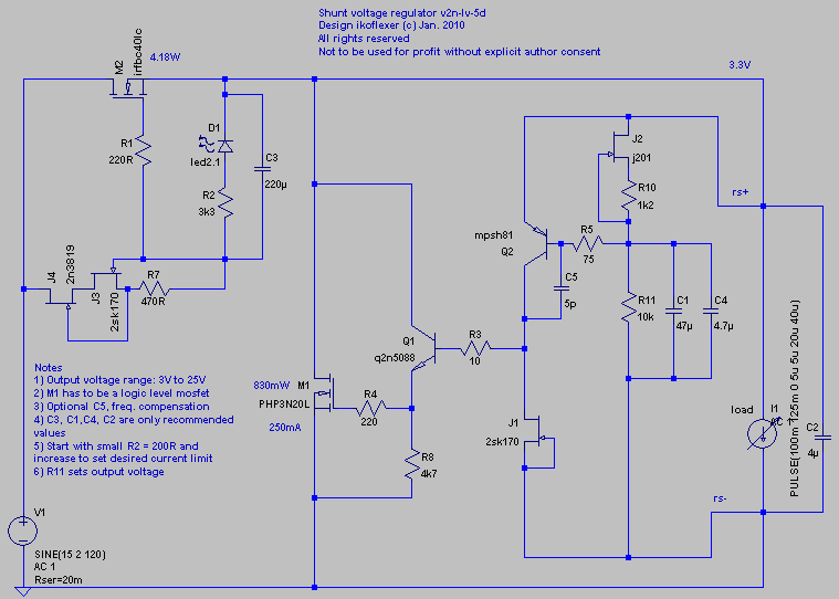
Although revision 5d works for voltages as low as 3V, the output impedance performance suffered as the voltage got below about eight volts. Here is the circuit which makes the performance for low output voltage as good as that for higher voltage.
This version works well 3V to 28V and can use the same PCB, but one must make sure the shunt mosfet can dissipate the heat. The shunt mosfet must be a logic level mosfet, meaning its threshold voltage V(th) should be small, typically between one and two volts. I tested it with a PHP3N20L but other mosfets should work, e.g. IRLU120. In the light of recent criticism that the design oscillates this time I decided to include C5, the frequency compensation capacitor. I hope a phase margin greater than 65 degrees will satisfy everyone.
Please do not take the capacitor values as set. Take them only as values in the ball park. These should work though, as shown, except for C2, the output cap whose value of 4uF should be taken as some ideal that we'd like to have, but a higher value would be more realistic. For instance my prototype used a 3.3uF film cap, and it worked fine. Those of you who don't have access to an oscilloscope to optimize this cap should use a higher value, 47uF, 100uF, etc.
There's probably something I forgot to mention, but I'll add some more comments later and answer questions if there are any.
He Iko,
this does sure look promising! Did you build it already? J2 is working at zero tempco, I guess? This is very low noise, but I had problems with drift with such a scheme despite a very careful adust procedure (with 2sk246).
I wonder as well how good the 'kelvin' connection for the voltage ref part will work. I had the impression, it was not as stiff as one would hope.
Very cool!
Rüdiger
I never liked Solen caps either. 220uF is a steep value but as long as is flexible (thanks Iko), I think we can experiment a bit.
For my new amp I have decided to not use any electrolitic below 470uF size, but there can be the case. I would try a Pansonic FM for C3.
The 470uf polyester cap i was referring to is the onein the pdf below:
http://www.kemet.com/kemet/web/home...9F08077848525769C0078BCC8/$file/F3301_JSP.pdf
For my new amp I have decided to not use any electrolitic below 470uF size, but there can be the case. I would try a Pansonic FM for C3.
The 470uf polyester cap i was referring to is the onein the pdf below:
http://www.kemet.com/kemet/web/home...9F08077848525769C0078BCC8/$file/F3301_JSP.pdf
Last edited:
Hi Rudiger,
Yes, built, tested, and stable. J2 works near zero tempco. I think it's too much hassle for a hobbyist to try and find the zero tempco (by adjusting R10). It is indeed very low noise, much more so than a zener diode. It also drifts a bit with temperature changes (millivolts), which is something that I accepted. My thinking is that for most audio circuits a few millivolts deviation should not make a difference. I'd rather have this than the noise of the zener. One can easily modify the circuit to use an ultra-low noise voltage reference if no temperature drifting is required. If I was building an measurement instrument that needs to stay within calibration I'd definitely do that.
Thanks!
The sensing works. Tested in the real circuit, no oscillation if that is what you mean by "not stiff." Are you referring to something else?
He Iko,
this does sure look promising! Did you build it already? J2 is working at zero tempco, I guess? This is very low noise, but I had problems with drift with such a scheme despite a very careful adust procedure (with 2sk246).
Yes, built, tested, and stable. J2 works near zero tempco. I think it's too much hassle for a hobbyist to try and find the zero tempco (by adjusting R10). It is indeed very low noise, much more so than a zener diode. It also drifts a bit with temperature changes (millivolts), which is something that I accepted. My thinking is that for most audio circuits a few millivolts deviation should not make a difference. I'd rather have this than the noise of the zener. One can easily modify the circuit to use an ultra-low noise voltage reference if no temperature drifting is required. If I was building an measurement instrument that needs to stay within calibration I'd definitely do that.
I wonder as well how good the 'kelvin' connection for the voltage ref part will work. I had the impression, it was not as stiff as one would hope.
Very cool!
Rüdiger
Thanks!
The sensing works. Tested in the real circuit, no oscillation if that is what you mean by "not stiff." Are you referring to something else?
You mean the simplistic with a buffer? Yep, pretty much the same thing. Comes down to your taste buds, n vs p 🙂
Edit: I don't really get the intention of your message though. Should I delete the circuit and just point to the simplistic? The reason for posting it is because I was able to get the output impedance below 1mOhm at low voltage, which was not the case with 5d, even though 5d will have better performance at voltages above 10V.
Edit: I don't really get the intention of your message though. Should I delete the circuit and just point to the simplistic? The reason for posting it is because I was able to get the output impedance below 1mOhm at low voltage, which was not the case with 5d, even though 5d will have better performance at voltages above 10V.
Last edited:
no, nothing to delete.
Only remark, that this circuit looks to me very similar to Simplistic, with P and N parts exchanged.
Only remark, that this circuit looks to me very similar to Simplistic, with P and N parts exchanged.
Of course it is, because I started with the simplistic and made changes to achieve what I was looking for; some of the changes are in the topology of the error amp, some are not as significant. At some point even the little details will make or break a circuit. Some could complain that this is bad engineering. So be it, everyone's entitled to an opinion. Here's a summary of what happened after I came in contact with the excellent Simplistic of Salas.
For wider output impedance bandwidth I added the bjt buffer before the shunt mosfet. The output impedance was curving up beyond 10kHz before, but after adding the buffer it became flat in the audio frequency (better phase profile too) and beyond.
Then I changed the error amp to a cascode, to lower even more the output impedance.
But, as soon as you get low impedance even at high frequencies it's highly likely that the circuit will oscillate. Many people will quickly reach for one or more compensation capacitors. But this, in my opinion, is not the general best way of dealing with this problem. So in came the RF bjt.
And then there is remote sensing. That too came after lowering Zout.
Changed the CCS for several reasons: removed R1 from the signal path. At large currents I had trouble adjusting R1 because its value was becoming very low, order of hundreds milliohms, and a tiny change in R1 results in a large change in current. I'm not saying it is wrong to do it that way, just that I preferred to adjust the current the way I do it now, which is a bit more forgiving IMHO. Also, this way it was easier for me to use the CCS unchanged for the negative version as well.
Another change, re-did the whole circuit using n-channel mosfets, to make it more accessible to people. Again, it's just an opinion, that there are more n-channel mosfets to find around, since I'm a big fan of having options.
I also tried to get rid of using 2sk170 because it is harder to find, so I looked into other jfets that would ultimately have the same regulator performance.
Lastly, at the time I first came across the simplistic, publicly it was using a zener as Vref. I measured it and decided that it was noisy, so I decided to change it to the Vref using jfet+resistor. Did it, measured it, tested it. It turns out Salas was onto the jfet Vref for a while, but I did not know it, nor did I see it publicly used in the simplistic (or privately).
Now back to the low voltage version that I just posted. The cascode is in the way because it doesn't have enough head room. But removing one of the bjts from the cascode allows it to work well again with low voltage. I brought back the 2sk170 there, instead of the 2n3819 because it has a lower pinch off voltage which is what we want when we don't have much voltage to work with.
Phew! 😀
Iko, my remark re the voltage ref wasn't meant to criticise, just curiousity.
I have yet to find a simple enough reference as silent as a fet, and at last a bit more constant in temperature as this fet.
With 'stiff' I meant voltage drift.
I for myself took a different route, I simplified the shunt reg even more and still get around -90dB and an output impedance around 0.3R, flat until ~100kHz. They are intended as local regs.
Rüdiger
No worries, indeed I thought your comment was a remark. I guess I'm over-explaining my choices a bit too much.
I'm a big fan of simpler circuits actually. But I couldn't get below milliohm output impedance with a simple circuit. If your reg is good for what is intended, it's all that matters.
I too wish there was a better Vref option, if you come across one please give me a shout. 🙂
I'm a big fan of simpler circuits actually. But I couldn't get below milliohm output impedance with a simple circuit. If your reg is good for what is intended, it's all that matters.
I too wish there was a better Vref option, if you come across one please give me a shout. 🙂
Hey guys, this is the philosophy of these threads. Its not about achieving something but about playing and learning and building. I did something reg for the phono in 2008 with the soldering iron and the ear mainly, based on stock leftover semis. 2SKs left over unused from the non matching for the phono, and IRFP9240s I had for amps. Checked DC and transient first on err... simplistic 😀 simulations. OK it was not based on thin air, had a concept and some princples and some sonic evaluation, but was not some engineering goal either. Had in mind a bro reg for the phono that had to be simple too and sound OK together. If it was something of a super duper performance & zillion parts thing, nobody interested in the particular phono would make it. Out of concept it would be. There are real engineers here that have irreproachable open projects threads. But its all about the feeling of creation that some laymen DIYers like me try our own. After a circle of friends used it too and all were happy in all layouts and on several other audio circuits, it continued to get practical for many members here too. Its no matter how good is something in absolute terms, its more about how ''adequate'' it is and to whom. If you followed the phono thread you would see that it was more of a live report of ideas and experiments than a '''take that, use it, and shut up'' 10 posts telegraphy and vanish. And then the builds came along and the versions and the parts selections etc etc. Many times many repetitive simple questions too. A collective DIY happy corner non the less.
Then Iko came in and did something very nice. Explored the concept, geared up simulating, and by reading and learning and making along, he kept the interest for the shunt reg part going. I thank him for that, he got me to think about it further too, and brought attention and explanation and tests from other members too. So it does not matter how near or not the versions will look or sound, in the end we will surely have flavor tones and resolution gamut for synergistic choices even. Only even the different semi parts will give character. Hey, thats rich DIY. If some people listen better due to those circuits as they get to report, then this is a hobby job well done IMO. Now if sorcerer's apprentices like me and Iko flood the lair once a while, OK give us some slack, we will upgrade our spells with age. 🙂
🙂
Then Iko came in and did something very nice. Explored the concept, geared up simulating, and by reading and learning and making along, he kept the interest for the shunt reg part going. I thank him for that, he got me to think about it further too, and brought attention and explanation and tests from other members too. So it does not matter how near or not the versions will look or sound, in the end we will surely have flavor tones and resolution gamut for synergistic choices even. Only even the different semi parts will give character. Hey, thats rich DIY. If some people listen better due to those circuits as they get to report, then this is a hobby job well done IMO. Now if sorcerer's apprentices like me and Iko flood the lair once a while, OK give us some slack, we will upgrade our spells with age.
🙂- Status
- Not open for further replies.
- Home
- Amplifiers
- Power Supplies
- My take on a discrete shunt voltage regulator