HiFi nut,
I don't think you are right to place all the blame on the local decoupling. It seems to me that some of the blame goes to the regulator design and some more of the blame goes to the builder and the haphazard way of playing with component values.
Andrew,
There is no blame! 🙂🙂🙂 No blame on the regulator. No blame on the local decoupling. No blame from myself on my bad build. No blame on any comments, positive or negative.
It is part of a learning process for me!

Regards,
Bill
I see now that you're using a resistor in series with the output capacitor. I should say, on my prototype I always used a capacitor alone.
Regarding the large capacitor at the output. There might be a very large inrush current. You might want to use an ntc thermistor as inrush current limiter. I got a few out of some smps and use them in prototypes until I make sure things work as they should.
The resistor is to pad sufficient "ESR" to the cap. It is not in series with the output, or it defeats the purpose of the low impedance regulator.
Would the inrush current be limited by the CCS? I thought there is no worry on this. I could be wrong.
But to fill up 4,400uF (I guess that would be the maximum value required, and actually 1,000uF may do because it is to damp the resonance caused by parasitic capacitance, which is small, in the case of no local bypass) would take less than a few seconds. The MOSFETs can operate at 150 degree temporature so I guess the chance of blowing up the CCS MOSFET is remote. There should be no danger to any other components other than the CCS MOSFET. Correct me if I am wrong.
Last edited:
Yes, your current limit is pretty low, you should be fine. If your current limit was larger, at start-up, the CCS mosfet would get almost the entire voltage drop across it at that current.
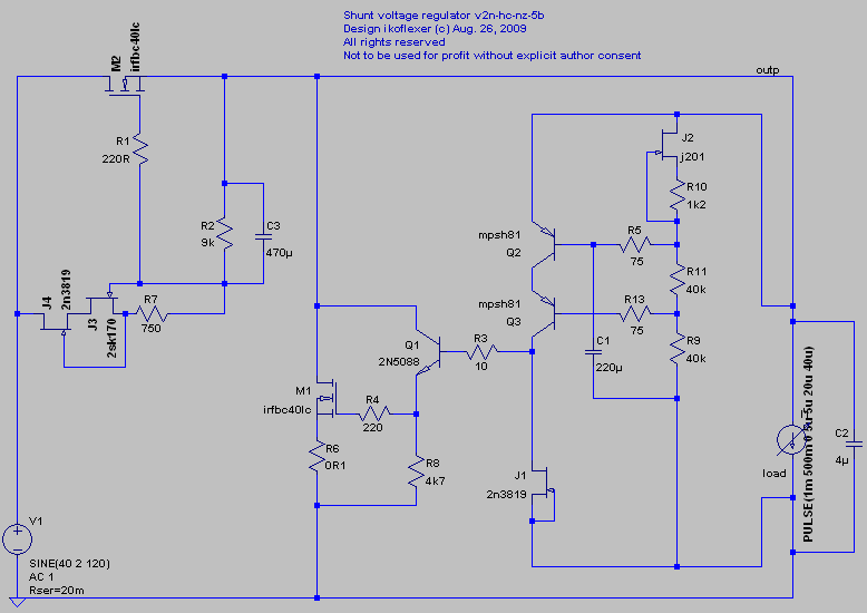
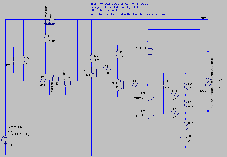
A small update, revision 5b of v2. Moved C1 to attenuate the Vref noise better.
Positive
Negative
Positive
Negative
Did you do it in practice also? Some transistors can latch low when they see the cap directly. Seldomly but I have seen it happening.
I don't think it will over large enough resistors, but do it in practice to be certain too, it does filter better with RC constant. If you ever bump into something like that, either get the cap lower value or the stopper. There is nothing that indicates it here, just test for anti jinx's sake.
The truth is I've done too much talky-talky lately, and not enough soldering 😀 I hear the call of the wild!
I test an SE Mosfet ccs'ed headphone buffer with shunt reg as we speak.🙂 AKG 701, Grado SR60. 701 is a pig needs gain. SR60 happy.
The resonance is now removed. The scope shows a thin flat line.
I have not had enough time to do the remote sensing stuff. Modelled with LTSpice that a super large cap + resistor won't damp the resonance in this case, or they had to be some ridiculous values that I won't trust LTSpice based on assumptions. However, a 22uF(ESR=0.34) local bypass would damp the resonance. I tried it. It worked.
So the resonance came mainly from the wire inductance and parasitic capacitance. It is not the regulator (by itself) that resonated.
The sound is overall clearer with the previous small degree of high frequency hash much reduced. But adding an electrolytic capacitor also added a tiny thin veil, not dramatic this time.
When I have the time, I will do the remote sensing stuff.

I test an SE Mosfet ccs'ed headphone buffer with shunt reg as we speak.🙂 AKG 701, Grado SR60. 701 is a pig needs gain. SR60 happy.
Headphones can be extremely revealing. Are you going to let us know the results or should I ask privately?
Its nothing much. An IRF630 CCS'ed underneath at half 18V B+ and 260mA I bias. 0.75A Vbe V1 for both channels. 100VA Tx 2X4700 Elna //, soft recovery diode bridge. Dead silent even on sensitive cans, you need a led to know its on. Has triode type sound. Good tempo and a little upfront but grainless. V1 helped it a lot. Fleshes it out. I need to add a gain stage for insensitive headphones too on input 2. Anyone know a single psu opamp that is cheap, easily available and has smooth sonics?🙂
Clips early if simple common source. 2N5459 takes 2V p-p but at 6V p-p that CD is clips too. With available B+ that is.
Maybe I will use a normal +/- psu op amp from my drawer by creating a virtual ground, ...it will need yet another ac coupling on its input.
I don't know, but I built two different phono stages based on opamps. Tried various opamps too. Then built your discrete phono and there was just no contest.
Its not something to keep. I was just helping a friend to finish it, because he stumbled. Its great for what it is, and I just want it to have an add on for his low efficiency cans too. Its concept is to be a buffer for efficient headphones. Practical little project, not for critical purposes.
Anyone know a single psu opamp that is cheap, easily available and has smooth sonics?🙂
http://www.sg-acoustics.ch/analogue_audio/ic_opamps/pdf/opamp_distortion.pdf
pick up your favorite...🙂
- Status
- Not open for further replies.
- Home
- Amplifiers
- Power Supplies
- My take on a discrete shunt voltage regulator