I think what we want, is a gyrator with a high Q. In an inductor, the higher the Q, the more ideal the inductor is. Similarly, a gyrator has a Q, and, the higher it is, the better. What is wanted, I think, in a gyrator, is a really high impedance, in a wide as possible bandwidth.
Q = X_L / R
Where R is the internal resistance of the inductor (just like you measure it in a choke with the ohmmeter), and X_L is the inductive reactance. The higher the X_L is, and the lower R is, the higher and more ideal the inductor is.
Since a gyrator is trying to emulate an inductor, I think the same principles should hold.
In summary, I think that low output impedance is not what we want.
But, if that circuit sounds nice to people, I have nothing against it.
I'll see what we can cook up around here that makes sense technically too.
Yes I am shocked.
I will just check to see if he made any changes to this.
This is good news though. If this sounds much better than an LM317 as a pre-regulator.
Then it will be very easy to improve on this, given the results.
It goes to show it doesn't take much to beat an LM317 as a pre-regulator.
I will just check to see if he made any changes to this.
This is good news though. If this sounds much better than an LM317 as a pre-regulator.
Then it will be very easy to improve on this, given the results.
It goes to show it doesn't take much to beat an LM317 as a pre-regulator.
Last edited:
Do you remember when I said that I will not use a lm317? 🙂
I don't know if it will be easy to improve, but we can try. Eventually we should be able to get something better. It would be nice to get something significantly better. Good challenge, eh?
I don't know if it will be easy to improve, but we can try. Eventually we should be able to get something better. It would be nice to get something significantly better. Good challenge, eh?
I am glad that you guys are continuing your progress. I am not a designer but only a builder and an "audiophile".
I am happy to help save you time and build the thing and test it for you once you guys work out and publish a design.
I have just got a signal generator and an oscilloscope to play with. I hope it is helpful in testing new builds.
I am happy to help save you time and build the thing and test it for you once you guys work out and publish a design.
I have just got a signal generator and an oscilloscope to play with. I hope it is helpful in testing new builds.
Just some more info.
Apparrently we need to get the ripple at the output of cap multiplier to around 1mV or better
Apparrently we need to get the ripple at the output of cap multiplier to around 1mV or better
The more I am thinking about this, the more I think a CLC with some large polypropylene motor run caps at the output would be better.
The other option might be two salas regs in series, the first one acting as the pre-regulator.
For some reason the quality of the caps may play a bigger role than the simulated performance shows.
It is very easy to get the output impedance down on the mosfet cap multi you just need to put 15000uF electrolytic and 40uF film (paralleled) at the output.
OK this is the first time I used an oscillioscope.
The output capacitor is the 1.1uF + 0.5R on v2. The load is dummy one of a 5W wirewound resistor of 680R.
Put the scope at the output. Found only one resonance at 10mV peak to peak at just below 20MHz, which is close to the highest the oscillioscope can go (0.5u sec with about 10 sinewaves within one grid and the height of the wave is one grid with voltage set to 0.01V, or is my interpretation of the reading wrong?).
I changed the 0.5R to 1R. The resonance was gone. Only a thin flat line across 1Hz to 20MHz.
So I was very happy. Then I removed the resistor dummy load and put on the real load. The real load had only an OPA627 buffer. There was no local bypass. I have to confess I have not done the changes to the layout yet. So the PSU wire is still the 15A thick cable running at 13cm long.
Checked with the scope, found the 20MHz resonance came back! About 10mV on one rail and 8mV on the other.
Tried local bypass by adding a 0.01uF directly at the opamp supply pins. Checked with a scope, found a new resonance at about 3MHz of 50mV peak to peak, superimposed onto the 20mHz resonance. This time, using a DMM on the output of the opamp showed swinging voltages between -0.3mV to +0.5mV. Previously it was stable at 0mV and -0.3mV.
Last edited:
So it seems like:
(1) Using a 1.1uF + 1R output resistor, the regulator does not resonate.
(2) It is the interaction between the regulator and the load that is important.
(3) I have a lot more work to do, and so far have no answers for the problem.
Any ideas?
(1) Using a 1.1uF + 1R output resistor, the regulator does not resonate.
(2) It is the interaction between the regulator and the load that is important.
(3) I have a lot more work to do, and so far have no answers for the problem.
Any ideas?
Would force/sense solve the problem?
Interestingly, in the Jung Supereg discussion thread, remote sensing has a lot more chance of oscillation than without. I guess the pre-assumption would be the use of local bypass.
This seems the result of the investigation with a scope matches my subjective experience that adding local bypass messes up the sound, as indicated in the above example 5 times worse resonance at much lower frequencies.
from post100
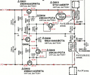
The cap multiplier will work better if R15 is moved to be parallel to C6 and the former location of R15 filled with an extra capacitor.Some people use capacitor multipliers before the regulator. Something like this can improve the psrr even more, at the cost of a few parts and a voltage drop of a few volts. I haven't tried it yet in a real circuit, it's just to throw the idea in for discussion.
HiFi nut,
is this a fair summary of what you have?
Take a regulated PSU that has a resonance and suppress the resonance with an RC combination.
Now add a pair of long cables with inherent inductance and capacitance and add a further capacitance at the far end of the inductor. This brings back the resonant characteristic of the regulator.
That to me seems like a guarantee for peaking in the FAST opamp load.
I don't think you are right to place all the blame on the local decoupling. It seems to me that some of the blame goes to the regulator design and some more of the blame goes to the builder and the haphazard way of playing with component values.
Hifinutnut, what about trying the real load with very short wires connection? Just for testing. Also, what output capacitor value is right now on the regulator?
Andrew, please disregard that circuit, it's a waste of time. I simply put it up to open the discussion about cap multipliers and gyrators.
Andrew, please disregard that circuit, it's a waste of time. I simply put it up to open the discussion about cap multipliers and gyrators.
HiFi nut,
is this a fair summary of what you have?
Take a regulated PSU that has a resonance and suppress the resonance with an RC combination.
Now add a pair of long cables with inherent inductance and capacitance and add a further capacitance at the far end of the inductor. This brings back the resonant characteristic of the regulator.
That to me seems like a guarantee for peaking in the FAST opamp load.
I don't think you are right to place all the blame on the local decoupling. It seems to me that some of the blame goes to the regulator design and some more of the blame goes to the builder and the haphazard way of playing with component values.
So it is the regulator I built and more likely the way I built it caused resonances. That may very well be the case. Can you come up with something to help solving the problem?
Last edited:
Hifinutnut, what about trying the real load with very short wires connection? Just for testing. Also, what output capacitor value is right now on the regulator?
Yes this may be something to try. The trouble is that I have limited space left on the regulator board. The output capacitor is 1.1uF + 1R.
I have a few things in my mind:
1. Try your suggestion, i.e. moving the OPA627 directly on the regulator board. The problem is that the regulator is to drive multiple opamps so this won't work in real demands, but only serves the purpose of testing.
2. Use remote sensing, if this has the same effect as moving the OPA627 to the regulator board.
3. Use a very large capacitor with a resistor, e.g. 4,400uF + 0.5R at the output of the regulator. This will have a very good chance of damping the resonance caused by parasitic LCR. Because a shunt is by nature a short circuit, and the CCS limits the current, I don't think there will be any adverse effects (i.e. damages) by using a super large capacitor at the output.
Andrew presumed that there is a resonance from the regulator. The 1.1uF + 1R was only to surpress it. Although this is one posibility, I am not convinced this is the case yet. All regulators are inductive at their output, the interaction to the load with wire length and parasitic capacitance will create some resonances, even if the regulator does not resonate by itself. I modelled this quite a bit using LTSpice. Regulators are usually not the objects to be blamed. Working out the layout, local bypass, etc, should be considered as an important part of the build. In other words, I consider what I am doing now is part of completing the build process.
From that point of view, and presume that the regulator does not resonate by itself, what is wrong using RC to damp the parasitic resonances?
In theory the remote sensing connection we've talked about would work just as well as short wires at the output. I haven't tried it yet myself on v2.
I see now that you're using a resistor in series with the output capacitor. I should say, on my prototype I always used a capacitor alone.
Regarding the large capacitor at the output. There might be a very large inrush current. You might want to use an ntc thermistor as inrush current limiter. I got a few out of some smps and use them in prototypes until I make sure things work as they should.
- Status
- Not open for further replies.
- Home
- Amplifiers
- Power Supplies
- My take on a discrete shunt voltage regulator