"Hi all,
I've experimented with two different types of FET for the gyrator and come to an interesting conclusion. I compared the IRF610 with IRF 520, with a week of each in a circuit.
The IRF 520s comprehensively outperform the IRF 610's, even though the latter are a faster lower capacitance device. The IRF 520's have one significant advantage. They have a higher gfs, and therefore a lower on resistance. Drawing up the equivalent circuit shows the stability and high value of gfs to be the most important element of the FET gyrator. The IRF 520 has a gfs that is 3-4 times higher than the 610 at 4 S. Output impedance is roughly the inverse of this at approx 0.25 ohms, but only at high currents. I'm now trying to maximise the gfs of the FET either by finding a better device or by biasing it better. The standard idling current of a naim pre amp is not realy sufficiant to get the IRF 520 into the area where its gfs is greatest of most stable with Vds variations. I'm planning on loading the FET output up with high wattage resistors to draw more current and then heatsinking the FET properly. Things are going to get warm, but I expect a further reduction in output impedance to be audible. Parallelling up the FETS as well as pulling more current through them will help further.
Anyone know of a FET with a higher gfs than the IRF 520's?
I found the IRF 610 reduced the depth of the bass, reduced the channel seperation and made the sound field very small. IRF 520 opened thing out a lot and the bass tightened and deepened. I hope there is more of this improvement to be had."

"Having found improvements (to my ears) by switching from an IRF610 to an IRF520 on my gyrator I noticing that the principle difference between the two was the higher Gm of the 510. Gm in these devices tends to increase with drain current, as well as becoming more linear with Vgs variations. So I put a couple of heatsinks on the FET's and started loading the source of the FET to earth with 470 ohm resistors. The result is a noticable improvement in the bottom end and mid, with both becomeing more natural. The output impedance has reduced and the improvements are similar to those wrought by using better quality and oversized transformers.
I could take this further, with greater load resistors and more FET's in parallel if worthwhile. I suspect the capacitor on the FET's output could have a significant sonic impact as well, and will try reducing its value and improving its quality in due course. I'll try and take some current measurements at the weekend to see where the devices sit on the data sheets Gm graph. I suspect I'll need as much as an Amp to reap all the rewards this can give, but this will be at the cost of as much as 40W of wasted heat generation. The load could be switched out of circuit when not listening, and this would also allow A/B comparisons." John.Luckins
I could take this further, with greater load resistors and more FET's in parallel if worthwhile. I suspect the capacitor on the FET's output could have a significant sonic impact as well, and will try reducing its value and improving its quality in due course. I'll try and take some current measurements at the weekend to see where the devices sit on the data sheets Gm graph. I suspect I'll need as much as an Amp to reap all the rewards this can give, but this will be at the cost of as much as 40W of wasted heat generation. The load could be switched out of circuit when not listening, and this would also allow A/B comparisons." John.Luckins
I don't know, it's pretty confusing to me, because I don't know what the guy is trying to optimize; well, obviously the sound. But from a technical point of view, I don't know. He talks about gm, and this and that. Can anyone tell me what makes a good gyrator? To me it would be the ability to behave like a large choke. Are there any subtleties that I'm missing?
Obviously. How much gyro is in gyration.🙂 But then again the elements must have had some impact to his output impedance?
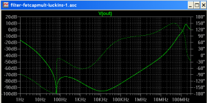
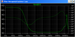
The biggest message that came out was that, the mosfet gave ultra-flat wide bandwidth output impedance, compared to bipolar darlington which is up and down with frequency.
He felt that by going for higher Gm mosfet he could lower the output impedance.
But again the biggest benefit comes from flat wide bandwidth output impedance espescially important at low frequencies.
He felt that by going for higher Gm mosfet he could lower the output impedance.
But again the biggest benefit comes from flat wide bandwidth output impedance espescially important at low frequencies.
Last edited:
Got shocked for imagining how to p2p perfboard that!🙂

Perhaps you prefer the Anatolyi way 😀

The biggest message that came out was that, the mosfet gave ultra-flat wide bandwidth output impedance, compared to bipolar darlington which is up and down with frequency.
He felt that by going for higher Gm mosfet he could lower the output impedance.
But again the biggest benefit comes from flat wide bandwidth output impedance espescially important at low frequencies.
I'd be really surprised to see a gyrator with outstandingly low output impedance. A good shunt regulator following the gyrator would provide that.
Than, if you could please point me to the particular gyrator that ended up with the wide bandwidth output impedance it'd be great. I'd like to do some analysis on it.
Last edited:
See Post 116.
I never said the output impedance was low (I think it might have been around 1 Ohm or less). I said it was flat with frequency compared to the bipolar darlington.
The absolute output impedance (while still important) does not seem as important as having flat output impedance for the pre-regulator stage. The bipolar darlington didn't have flat output impedance.
That is what they experienced, and hypothesized flat output impedance is important.
At least they were absolutely convinced Mosfets wipe the floor with Bipolars, when it comes to Audio performance. The ear wants to hear what the ear wants to hear.
They could be completely wrong about their hypothesis, but the audible improvements were obvious.
I am sure the combination of minds here can improve this simple pre-regulator.
Lets keep it simple though.
They also found film caps were significantly better than electrolytics, in the audibility department.
Last edited:
I want to understand this correctly. Was there anything else between the gyrator and the amp/preamp?
Walt jung super regulator, comes after the capacitor multiplier.
The walt jung super regulator comes with LM317 pre-regulators.
They removed the LM317 pre-regulator and put in a capacitance multiplyer before the super regulator. The improvements were not subtle. That is to say they noticed Bloody good improvement.
They first used a bipolar darligton cap multiplier but later found the mosfet cap multiplier was even better.
Just so there is no confusion, please do not build the Walt Jung Super Reg. The Salas reg is better. We are talking about the pre-regulator (capacitance multiplier) here.
Last edited:
- Status
- Not open for further replies.
- Home
- Amplifiers
- Power Supplies
- My take on a discrete shunt voltage regulator