Would you place the output cap near the shunt MOSFET output whether remote sensing is used or not? physically it could be placed anywhere from the output to right at the sensing point.
We'll see, it all depends on whether something better than the trivial comes up.
I would say where the sensing points meets with the load and the power lines from the shunt.
I would say where the sensing points meets with the load and the power lines from the shunt.
Hello all.
I have become interested in the Shunt scene.
I was wanting to obtain some measurements/figures from the latest reg here so I could set a benchmark for my own design ideas. More specifically, I want to know the output impedance value for the flattest area of the curve.
Have you simulated with typical ESR and ESL values for C1 and C2? I'm curious how much of an effect there would be.
EDIT: In fact, I could have just asked for the LTSpice files. Can someone please upload them? 🙂
- keantoken
Post 1 has the plots you want. For all caps I used ESR of 1R. C2 ESL of 10nH and C1 ESL of 15nH. I know, these are exaggerated, but that's exactly what I'm trying to do, simulate a somewhat sloppy build, and still get good performance.
Zout at 100kHz is about -88dB, or about 36uOhms which, is pretty academic of course, because in the real world one has to deal with a number of issues.
I have other versions that simulate even better (one I showed you in the Aspen HP amp thread) but they don't make a good overall regulator, IMHO. This one here is something that has more specs that I think are desirable in a real circuit.
If you'd like to play with it I can send you the file.
There's been discussion all over the place about how desirable low impedance is in a regulator. This design promises low impedance and here we go, we build it, we connect it to the load, super! It all works. But... there's a but, yes. It so happens that there is a distance of 5 cm between the load and the regulator. The guy who built it carefully read through the comments here and decided to follow our advice and use relatively thick, solid copper wire of 1 mm diameter.
After looking at the output impedance plot in post #1 our user knows that 36 microohms output impedance is not of this world, but he still hopes that in reality he'd still get something below 1 milliohm. Will he?
The inductance of 5 cm of 1 mm diameter copper wire is about 45nH. What happens to the output impedance? It goes up to about 404 milliohms.
This is all still theoretical, a simulation. But it illustrates the point and we should expect probably even worse effects in real life.
Proper implementation is really essential. To have any hope of low output impedance, remote sensing is not an option, but becomes necessary.
Thanks for the advice... I wish it was easy to test PCB layouts by the dozen and see what works and what does not. I was asking about Zout because I couldn't tell the exact number from your graph.
So, wires should be as short as possible, remote sensing done by shielded cable.
My current design has 60uohms at 100KHz, but 11uohms between 5k and 10Hz (the MOSFET used has much influence on Zout, here I use IRF9240). It is reasonably well-behaved, when compared with your stress test (although mine is with a 47u, .01ohm ESR bypass). It is completely un-Salas, and a little more complex. I'm using an incredibly fast implementation of the Rush Cascode (very well suited to regulators, if you're not scared away by tempco and its other weirdness).
Only in simulation though. With proper layout, how close to simulated performance do you think we can get?
Thanks,
- keantoken
kt, there's one big hurdle to cross, before even thinking about zout in reality. And that's stability. As soon as you get low zout numbers past 20kHz, stability becomes a huge issue. Sometimes you can get away with compensation caps, if you're not far from stability. I make it a point to build the prototype to see that at least is stable, or if not, to investigate how to make it stable. You may want to test yours especially now that it simulates with good performance and wide bandwidth. If you already did, then disregard my comments.
If stable, then only reality can give you the actual answer, I wouldn't venture. The way I look at it is, if the design promises good performance, and both the stability analysis (not that I trust it so much) and real circuit stability is good, then the better implementation you have the closer you'll be to the ideal result given by simulation. In my view the corollary holds too: if it simulates huge output impedance, how in the world can one expect it to perform well in real life?
Just my 2c, I'm a beginner. The experts may disagree.
I would say where the sensing points meets with the load and the power lines from the shunt.
Ikoflexer, my scope does not agree.
I rearranged some tracks and enabled remote sensing. The output cap (1.1uF + 1R) was not at the output but at the sense/load point. Measured a couple of 60mV resonances at the output, reduced to about 15mV at the load.
I then removed the "local" bypass (1.1uF + 1R), and put a 22uF(0.34R ESR) ZL at the output. A thin flat line appears in the scope at both the load and the reg output.
So it seems that the regulator needs an output cap at the output.
Retested the 1.1uF + 1R at the output with remote sensing. 15mV appeared in the scope again. This tells me that the output cap is not large enough.
OK, I am going back to do more soldering. I will gradually increase the output cap until I see a thin flat line in the scope.
When you say resonance, what do you mean? Would you be able to take a picture of it? Does it look like a sine wave, or does it look like a spike that occurs from place to place? If the spike, crest, or wave repeats on the screen, how many divisions are there between the two of them on the screen, and how many mS/div was the setting on the scope? I'm trying to infer the frequency of the blip.
Also it would be good to know if the blip goes down in size with higher current.
Another thing to consider, how is the grounding done?
They are waves repeating. I set the voltage to 0.01V (lowest) and the time at 0.5uSec (shortest).
Anyway, it was quite late so I did not do any further. I put the 22uF back in the output without local bypass (this gave a thin flat line) and put on a LM4562 to have a listen. The LM4562 had never sounded so good, nearly as good as the OPA627. The downside was at the very high frequency, the LM4562 sounded bright.
So I think I will give it a harder test tonight or tomorrow - play music when monitoring the rails and see if I find any ripples or "TAILS".
I think my earlier thought that "the output cap must be at the output" was pre-matured. I did not have sufficient evidence to support that statement so more tests are to be done.
In whichever case, things are improving and this is closer to my expected result.
With all these experiments, it points to low impedance and low inductance to be the key to success. That is never easy to achieve.
They are waves repeating. I set the voltage to 0.01V (lowest) and the time at 0.5uSec (shortest).
Good job hifinutnut. Do you remember by any chance how many vertical lines distance between the peaks of the waves?
I just realized that the MPSH81 is an RF transistor... I was sort of puzzled by the incredible bandwidth of the simulated circuit. Hmmm. And the 2N5088 is a high-gain transistor, to keep from loading it's high source impedance.
Does R6 have a large affect on stability?
And why use different FETs for J1 and J2? Wouldn't one type work for both?
The circuit is simple enough that it could be SMD'd and put right at the voltage input of the subject PCB, rather than on a whole other PSU dedicated board and associated lengths of wire.
Thanks,
- keantoken
The waves were different from each different set of value of output cap and its location. They were 2 to 10 of (sometimes superimposed) sinewaves within each grid so the frequencies were between 4mHz to 20mHz with magnitude between 3mV to 50mV, also depending on where the plobe was.
But the simpliest of putting a 20uF (ESR=0.34R) at the output, without local bypass, with remote sensing, gives a thin flat line with no resonances. However, this is when there is no music signal and the load is purely from the bias of the opamp, a constant load. I will need to test when music is playing and see if it can trigger any ringings on the rails.
But the simpliest of putting a 20uF (ESR=0.34R) at the output, without local bypass, with remote sensing, gives a thin flat line with no resonances. However, this is when there is no music signal and the load is purely from the bias of the opamp, a constant load. I will need to test when music is playing and see if it can trigger any ringings on the rails.
I just realized that the MPSH81 is an RF transistor... I was sort of puzzled by the incredible bandwidth of the simulated circuit. Hmmm. And the 2N5088 is a high-gain transistor, to keep from loading it's high source impedance.
Does R6 have a large affect on stability?
No, I use R6 to measure the shunt current in the real circuit.
And why use different FETs for J1 and J2? Wouldn't one type work for both?
It would work, but not the same. I'm keen on using j201 for J2, because of its properties in the Vref, but I prefer a higher current for J1.
The circuit is simple enough that it could be SMD'd and put right at the voltage input of the subject PCB, rather than on a whole other PSU dedicated board and associated lengths of wire.
I'm planning to design one, yes, for low current needs.
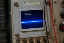
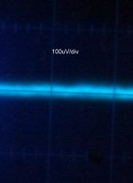
In post #164 C1 got moved to the base of Q2. Tonight I tested this mod and it was as stable as ever. Also, tested a 4uF film cap on the output and you can see the attached resulting trace images. The vertical distance between the faint lines in the image is 100 microvolts. The trace shows very little noise, mostly a flat trace about 10 to 15 microvolts thick.
The rest of the psu consisted of a transformer, followed by a rectifier, followed by a 10000uF capacitor. Don't take this as a suggestion, I just happened to have the rig setup this way from another project so I just used it. The DC voltage (if you can call those crests DC) at the regulator input was about 38V.
If anyone's wondering, I think this is it, v2 should stay pretty much as is. I've tested it even as a somewhat sloppy built and it was stable. For more current I've even tried two mosfets in the CCS and two mosfets in the shunt. The limit power dissipation will be set by the safe operating area of the mosfet and the size of the heat sink. Just tonight my screwdriver slipped a bit and the current went up to about 7A for about 20 seconds, but nothing got fried. The output voltage was set to 22V. Yep, the regulator dissipated over 100W for a short time. 😀
As I said before, there are some build details described in post #1, but if anyone's considering building it and has questions, don't hesitate, ask away.
Attachments
OK then no problems with the C1 move. Did you manage to see any wee difference for noise uV with that move on the scope?
Not sure, the total noise is below what I can measure in microvolts. 🙂 The C1 mod makes sense though theoretically and if the rest of the regulator is built properly it should be beneficial.
At this point even moving the oscilloscope probe puts more noise on the screen.
The whole thing is so sensitive. I tried measuring the noise with the HP3581A wave analizer (also a microvolt RMS voltmeter) but as soon as the probes touched the output it infused about a 100uV noise from creating a ground loop, because now both the scope and the HP3851A were grounded.
I built a battery powered noise preamp last week or so which I used for testing the noise of different Vrefs but I forgot to hook it up to have a look tonight. Honestly, it's hard for me to worry about the regulator noise after in theory and in practice it show as you see.
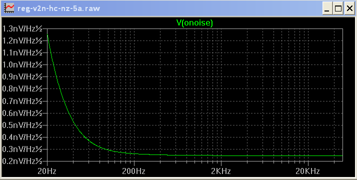
BTW, since I don't think I posted yet the simulated total noise at the output of the regulator, here it is, up to 50kHz.
At this point even moving the oscilloscope probe puts more noise on the screen.
The whole thing is so sensitive. I tried measuring the noise with the HP3581A wave analizer (also a microvolt RMS voltmeter) but as soon as the probes touched the output it infused about a 100uV noise from creating a ground loop, because now both the scope and the HP3851A were grounded.
I built a battery powered noise preamp last week or so which I used for testing the noise of different Vrefs but I forgot to hook it up to have a look tonight. Honestly, it's hard for me to worry about the regulator noise after in theory and in practice it show as you see.
BTW, since I don't think I posted yet the simulated total noise at the output of the regulator, here it is, up to 50kHz.
I know its academic, that is why I asked if you could see a hair thiner noise line. Maybe it does something when the ref isn't a big enough Norton, and the cap does see a difference between across a low impedance and with RC constant. Maybe with an LM ref Z diode for example.
I did some tests an hour ago. I connected my CD player to my preamp (opamp buffer) and played some music while using the oscilloscope to measure the preamp input and the regulator rails.
When the scope probe was at the preamp input, the screen displayed all those wonderful dancing lines.
When the scope probe was at the rails, whether at the regulator output end or at the load end, the screen displayed a thin, flat, straight, static line.
I thought I had to be careful so I checked very carefully and did it many times. The result was confirmed.
- Status
- Not open for further replies.
- Home
- Amplifiers
- Power Supplies
- My take on a discrete shunt voltage regulator