The set up is as follows:
v2 published a month ago (not the latest), built as per the schematic using perf board. Made shortest possible connections between transistors.
Tx (15V-0-15V) - 1N5822 - 3 x Panasonic FC 3,300uF || 1 x Rubycon ZL 2,200uF
1.1uF, 20k, 20k Vref
CCS current set to just above 100mA
Remote sensing.
22uF/50 Rubycon ZL (Imp=0.34R at 100kHz) at the output.
Replaced the LM4562 with the OPA627. That high frequency uneasiness I reported last night was gone.
In terms of regulators, this is the best I have had so far. The oscilloscope I got on Monday helped.
I will spend the next 2 days to select the best output capacitor (and its ESR) and then wrap this project up. I will then use this preamp to (re-)do speaker driver measurements, and will within weeks complete my active speakers.
Thanks to everyone who contributed, especially Ikoflexer and Salas.
Last edited:
My oscilloscope can only display 10mV a grid and 0.5uSec.
The thin flat line I referred to must be under 1mV. It did not look any thicker, actually a bit thinner than the screen picture from Ikoflexer in post 196, but with 10mV per grid. I wish the resolution of the scope can be higher.
One thing I noticed was that the line obviously brightened up when it was set to 5uSec, which corresponds to 2MHz per grid. So there may still be resonance at this region, but it must be very low in amplitude, no more than or at most 1mV for sure.
Last edited:
Ikoflexer,
I know you have inserted nH into capacitors and other tracks. Have you inserted some nH between Q1 and M1 via R4? This is where very low impedance output going into very high impedance input, including R4, the wire length must be at least 1.5cm so that is a 10.53nH at a minimum! I have not soldered R4 on the upper leg of M1, so I expect the inductance may be as high as 20nH! Could you please have a check?
Regards,
Bill
tested a 4uF film cap on the output and you can see the attached resulting trace images.
4uF? Odd value. You mean 2uF || 2uF? or a 3.9uF? What capacitors are they?
Please forgive me for what I am about to say.
Has anyone tried feeding the Salas reg with a switch mode power supply?
Has anyone tried feeding the Salas reg with a switch mode power supply?
When the scope probe was at the rails, whether at the regulator output end or at the load end, the screen displayed a thin, flat, straight, static line.
I thought I had to be careful so I checked very carefully and did it many times. The result was confirmed.

One thing I noticed was that the line obviously brightened up when it was set to 5uSec, which corresponds to 2MHz per grid. So there may still be resonance at this region, but it must be very low in amplitude, no more than or at most 1mV for sure.
Just an artifact of the scope. I think there would be more signs if you had oscillation.
4uF? Odd value. You mean 2uF || 2uF? or a 3.9uF? What capacitors are they?
Got it from a surplus store here in TO. Says "Ero MKC 4uF 200V" on it. Ugly green colour :d
Ikoflexer,
I know you have inserted nH into capacitors and other tracks. Have you inserted some nH between Q1 and M1 via R4? This is where very low impedance output going into very high impedance input, including R4, the wire length must be at least 1.5cm so that is a 10.53nH at a minimum! I have not soldered R4 on the upper leg of M1, so I expect the inductance may be as high as 20nH! Could you please have a check?
Regards,
Bill
Checked with a 25nH, doesn't change a thing.
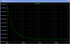
BTW, since I don't think I posted yet the simulated total noise at the output of the regulator, here it is, up to 50kHz.
Very excellent noise figures. This confirms what is stated in the Noro patent, i.e. that shunt regs should by much quieter than conventional regulators. It would be intersting to confirm this thru simulations of a good series regulator design, and if possible thru actual noise measurements, though I acknowledge that the latter is not trivial.
Thanks Martin. I happen to have the Jung SR file handy from the time I built it. Here's the noise simulation. I'm reluctant to take seriously any noise simulation, hence, I'd consider the noise simulation only for its entertainment value.
Regarding actual noise measurements, I agree, sub microvolt measurements are tough to do with any degree of confidence.
Regarding actual noise measurements, I agree, sub microvolt measurements are tough to do with any degree of confidence.
Attachments
Based on the successful experiment of 4uF film output cap by Ikoflexer, I did a number of experiments on the output capacitor today with my new remote sense configuration.
Since layout is important, I have to describe mine (which would be different from Ikoflexer's) so that we can discuss under the right context. There is a distance about 5cm from the shunt MOSFET to the output point, due to the space occupied by the heatsink and by the components. Form the output point to the load is 12cm. Sensing point is directly on the load.
When the output cap was placed at the output point.
Rubycon ZL 22uF/50V (ESR=0.034R) - no resonance.
4 x 2.2uF || Polyester - no resonance.
1.1uF MKP Vishay blue box - resonance with a magnitude of about 2.5mV.
6.8uF MKT Suzuki - resonance with a magnitude of about 8mV.
7.5uF/400V Solen - resonance with a magnitude of 40mV (No wonder I always found Solen to be unlistenable!)
The best so far is the 4 x 2.2uF || Polyester on the output.
I then put the 4 x 2.2uF || Polyester at the load and found there was a resonance of 8mV - 10mV.
The above seems to suggest that the output capacitor should be nearer to the MOSFET than the load, because for the same 4 x 2.2uF, when placed at the output it did not resonate, but it did when placed at the load.
If that is true, then in my final build of the regulator (I consider the current one to be prototype) I will place the output cap right next to the shunt MOSFET.
Can somebody give a technical reason why the output capacitor should be placed near to the shunt MOSFET (or otherwise)?
If that is true, then in my final build of the regulator (I consider the current one to be prototype) I will place the output cap right next to the shunt MOSFET.
Can somebody give a technical reason why the output capacitor should be placed near to the shunt MOSFET (or otherwise)?
Among those caps used, the Vishay blue box 1.1uF MKP should have the lowest inductance because the capacitor was designed for high frequency application. I guess the reason it resonated may be due to insufficient capacitance. But to make up 4uF I would need to parallel 4 of them per rail, which could occupy much space. So I guess I may choose the 4 x 2.2uF polyester because of the small space they occupy. they are also cheap and available.
So I have a feeling that the regulator may not like an output capacitor less than 4uF.
But it may depend on the layout and the load. I remember that before I used remote sensing, with a dummy resistor load (i.e. not the real load), I had the 1.1uF + 0.5R at the output and it resonated. When the 0.5R was increased to 1R it did not resonate.
Iko, got all parts except j201. Can I simply replace it with 2SK170? Using 2n2222 in place of 2n5088 which is not available here. Caps will be generic electrolytic for now.
....
When the output cap was placed at the output point.
Rubycon ZL 22uF/50V (ESR=0.034R) - no resonance.
4 x 2.2uF || Polyester - no resonance.
1.1uF MKP Vishay blue box - resonance with a magnitude of about 2.5mV.
6.8uF MKT Suzuki - resonance with a magnitude of about 8mV.
7.5uF/400V Solen - resonance with a magnitude of 40mV (No wonder I always found Solen to be unlistenable!)
....
You asked Iko about the strange 4uF MKT cap.... but as far ad odd numbers are concerned, you also have some uncommon values!
Joking aside, can you please specify the complete designation for the 1.1 uF MKP "blue box"?
Generally Ero/Roederstein now Vishay caps have 4 digits following MKP, such as 1822, 1830, etc. A Farnell/Digykey/other part no. will suffice.
Thank you!
pes/MKS/MKT are reputed to have a higher esr than PP/MKP. This difference would account for stability of the first two capacitor types and the instability of the latter three capacitor types, if the Suzuki has some special construction to lower it's esr.Rubycon ZL 22uF/50V (ESR=0.034R) - no resonance.
4 x 2.2uF || Polyester - no resonance.
1.1uF MKP Vishay blue box - resonance with a magnitude of about 2.5mV.
6.8uF MKT Suzuki - resonance with a magnitude of about 8mV.
7.5uF/400V Solen - resonance with a magnitude of 40mV (No wonder I always found Solen to be unlistenable!)
Any thoughts?
Iko, got all parts except j201. Can I simply replace it with 2SK170? Using 2n2222 in place of 2n5088 which is not available here. Caps will be generic electrolytic for now.
Yes, it would work. If you use the 2sk170 you're building a different Vref, so the resistors would be different. I'd set the current through Vref at about 15% of Idss.
The above seems to suggest that the output capacitor should be nearer to the MOSFET than the load, because for the same 4 x 2.2uF, when placed at the output it did not resonate, but it did when placed at the load.
If that is true, then in my final build of the regulator (I consider the current one to be prototype) I will place the output cap right next to the shunt MOSFET.
Can somebody give a technical reason why the output capacitor should be placed near to the shunt MOSFET (or otherwise)?
The big question is if this rule applies in all cases. I can't think of a reason why this works better than at the other end.

- Status
- Not open for further replies.
- Home
- Amplifiers
- Power Supplies
- My take on a discrete shunt voltage regulator