Yes, by using a conventional wiring of the secondaries you don't need the additional rectifier. The only effort is to rewire the power supply.
You could use a copper plate or bar to create the GND connection. Your buffer caps could be mounted with one of their terminals directly to the copper plate. The "CT" connection you create by wiring the two wires from the secondaries also connect to the copper plate. This is very common practice.
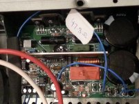
Thanks for the realtime support folks! Have quickly rewired one channel with one rectifier deleted and transformer configured as centre tap. Instead of a plate I have a little ring formed by the connections to caps, earth and the centre tap. Looks like a nightmare for EMI, but I can fettle with it later.
As expected I get 55.5V DC instead of 54.9V at idle, with additional diode drops. And it's much easier now to feed the Q-Watt with AC as intended. Should get even better overall regulation I expect with reduced rectifier losses.
Tomorrow then... fingers crossed. Pops.
You noticed Elektor's advice that the filter caps on the Q-Watt PCB aren't sufficient and you need at least one more pair that have to be mounted apart from the board?
Best regards!
Best regards!
Hi popchops.
Wish you well on switch on. Ensure you double check things.
a/. All transistors are isolated from the heatsink.
b/. Ensure all your Grounds are in place.
c/. Check that all of the metal surfaces of the case are Earthed.
Best to be safe than sorry, and anyway Delange and i have our ears tuned to Hertfordshire.
Although you've already read it in the Q-Watt article, here is some information below from it.
I'm sure your smoothing capacitors will be adequate.
Page 14:-
Two large buffer capacitors (4700 μF each) are also fitted on the circuit board. The selected types
have low equivalent series resistance (ESR).
The circuit additionally requires an external power transformer, bridge rectifier and four power supply capacitors rated at 10,000μF, 100V each.
Page 16:-
Power Supply (for one amplifier)
Power transformer: sec. 2x40V, 500VA (e.g. Nuvotem 0500P1-2-040 for 230 VAC mains)
Bridge rectifier: 200V, 35A (e.g. GBPC3502) (Fairchild)
Four 10,000μF, 100V electrolytic capacitors (2 in parallel on each supply rail)
As you know in the case of Delange and myself, we opted to use Switched Mode Power Supplies.
It works! (I think)
Got a red led and no smoke. No burned 47R resistors.
Initially measured 1.3V across the positive resistor and then tweaked the pot up to 2.7V. Should be about equivalent to the 30mA quiescent current.
Kay - I followed the Elektor expectations on the power supply almost to the letter, including 4x 10mF caps. Exception is my 420 VA transformer with 3.5% regulation instead of the 500 VA Nuvotem transformer with 8% regulation. Complete PS should hold up to hit the peak output figures ~139 Watts (8 Ohms). Nominal idle DC voltage is now 55.6V @240V input and this should never drop by more than 2-3V.
Thanks all for all the support. Will post more photos when I take some worth sharing. POPS.
Attachments
I use 230:dual 40Vac transformers for some amplifiers.
I find that when mains is @ 244 to 245Vac, the PSU when loaded with two amplifiers each drawing significant quiescent current gives between +-58Vdc and +-59Vdc.
This is good for >170W into 8r0 @ 1kHz no clipping. And the PSU voltage has dropped a lot more than 2 to 3Vdc.
I find that when mains is @ 244 to 245Vac, the PSU when loaded with two amplifiers each drawing significant quiescent current gives between +-58Vdc and +-59Vdc.
This is good for >170W into 8r0 @ 1kHz no clipping. And the PSU voltage has dropped a lot more than 2 to 3Vdc.
That's great news Popchops.
Just to mention again what Elektor stated: -
Connect an ammeter in series with the positive supply line.
Before switching on the supply voltage, turn P1 fully counterclockwise, and remember to connect the secondary windings of the transformer to terminal block K7 on the circuit board.
After the power is switched on, the current through the positive supply line should be approximately 30 mA when the output relay is engaged.
Slowly turn P1 to the right (clockwise) until the current increases by 30 mA (60 mA total).
Keep the fellow Q-Watt constructors posted, our Q-Watt ears are fully tuned, having placed 'our lives and project in our own hands' and sounds fab!
Last edited:
using a voltage dropping resistor in the power line is NOT a good way to measure and adjust output bias voltage.
When the resistor is replaced with a link, many amplifiers react with a large increase in bias voltage and can go into Thermal Runaway.
You should measure the bias voltage at the emitter resistors. And check all of them to see how different the dissipations of the various output transistors are.
When the resistor is replaced with a link, many amplifiers react with a large increase in bias voltage and can go into Thermal Runaway.
You should measure the bias voltage at the emitter resistors. And check all of them to see how different the dissipations of the various output transistors are.
Just to mention again what Elektor state in the Q-Watt article: -
Connect an ammeter in series with the positive supply line.
Before switching on the supply voltage, turn P1 fully counterclockwise, and remember to connect the secondary windings of the transformer to terminal block K7 on the circuit board.
After the power is switched on, the current through the positive supply line should be approximately 30 mA when the output relay is engaged.
Slowly turn P1 to the right (clockwise) until the current increases by 30 mA (60 mA total).
The Elektor Q-Watt article does not state "You should measure the bias voltage at the emitter resistors. And check all of them to see how different the dissipations of the various output transistors are."
Keep the fellow Q-Watt constructors posted, our Q-Watt ears are fully tuned, having placed 'our lives and project in our own hands' and sounds fab!
Last edited:
I use 230:dual 40Vac transformers for some amplifiers.
I find that when mains is @ 244 to 245Vac, the PSU when loaded with two amplifiers each drawing significant quiescent current gives between +-58Vdc and +-59Vdc.
This is good for >170W into 8r0 @ 1kHz no clipping. And the PSU voltage has dropped a lot more than 2 to 3Vdc.
Hi Andrew. Useful data.
I measured 3.4V droop on the overall PS with 167W resistive load. 55.3 dropped to 51.9. But that was heating two bridge rectifiers.
True, for 135W audio output I'll need about 192W from the power supply so I predict about 4V droop or 7%. I predict that will be the limit at 8 ohms, assuming 5V dropped in the amp.
But now, with only one rectifier I hope the regulation will be slightly improved.
[Primary resistance for the CW transformer = 2.2R, secondary resistance (each) = 0.2R]
Pops.
Last edited:
the transformer regulation does not change.
The PSU voltage will droop/sag as more current is drawn.
The PSU ripple will increase as more current is drawn.
The PSU voltage will droop/sag as more current is drawn.
The PSU ripple will increase as more current is drawn.
Sorry I was referring to the regulation/sagging of the power supply overall not only the transformer.
Hi Andrew,You should measure the bias voltage at the emitter resistors. And check all of them to see how different the dissipations of the various output transistors are.
Which are the emitter resistors for the Q-Watt? R8/9, or R10/11? Measuring voltage across the 0R2 is not practical for me.
Do you recommend the same process... measure voltage with pot dialled off anticlockwise and then tweak up whilst measuring across the onboard resistors?
What value of current is expected? Same 30mA?.
Sorry for going over old ground a bit. Ground hog day!
Pops.
Popchops, Elektor state in the Q-Watt article to do the following:-
Connect an ammeter in series with the positive supply line.
Before switching on the supply voltage, turn P1 fully counterclockwise, and remember to connect the secondary windings of the transformer to terminal block K7 on the circuit board.
After the power is switched on, the current through the positive supply line should be approximately 30 mA when the output relay is engaged.
Slowly turn P1 to the right (clockwise) until the current increases by 30 mA (60 mA total).
R10 and R11 are the emitter resistors (post6 .pdf).
Since the Qwatt instructions tell you to increase the current by 30mA to bias this amplifier, you will be able to measure 60mVre across 0r2
But have you fitted 0r2, or did you fit 0r22?
If 0r22 is fitted, then the voltage across one will be 66mVre and 132mVre2 across both.
Since the Qwatt instructions tell you to increase the current by 30mA to bias this amplifier, you will be able to measure 60mVre across 0r2
But have you fitted 0r2, or did you fit 0r22?
If 0r22 is fitted, then the voltage across one will be 66mVre and 132mVre2 across both.
The Cct diagram shows them as 0.2Ω
The component list shows them as 0.2Ω 1% 5W, low inductance (Vishay Dale
LVR05R2000FE73), and come as such in the supplied kit.
Popchops as i mentioned, in my Q-Watt, i did it exactly to the book, i.e. set the Q.Current to 30mA (allowing the amp to be left on for a while), and rechecked it after 5/10 minutes.
Hi Pops, just follow the Elektor instructions for bias adjustments. They work perfectly fine. There are several people here who did just that with great success.
It sounds great! At least the first channel, connected via croc clips to a disposable speaker.
Very very happy and now I know exactly what I need to do to finish.
Heatsink doesn't feel warm at all at low output levels? I expect it will all warm up a bit once I get above 10W.
Conveniently, 0.8mm solid core wire slides very nicely into the standard (Elektor supplied) input headers (audio in) so I am inclined to use this (twisted) to form the connection to the RCA terminals on the panel connector. Instead of coax cable, which is much stiffer and hard to maintain a 90deg bend without straining the ends.
Whatcha think? I cant hear any hissing... but second channel might change this.
Pops.
Three cheers for Popchops! 😉😀🙂
The larger Heatsink runs very cool and the small one of the i.c. runs cools too.
The larger Heatsink runs very cool and the small one of the i.c. runs cools too.
Thanks Andrew.R10 and R11 are the emitter resistors (post6 .pdf).
Since the Qwatt instructions tell you to increase the current by 30mA to bias this amplifier, you will be able to measure 60mVre across 0r2.
Is this correct? 60mV or 6mV?
Pops.
Hi Pops, just follow the Elektor instructions for bias adjustments. They work perfectly fine. There are several people here who did just that with great success.
Post #515
Popchops as i mentioned, in my Q-Watt, i did it exactly to the book, i.e. set the Q.Current to 30mA (allowing the amp to be left on for a while), and rechecked it after 5/10 minutes.
Last edited:
- Home
- Amplifiers
- Chip Amps
- My Q-Watt project