Awesome Calpe! You're some way ahead of me. I ordered transformers today so I'm 4 weeks away from finalising the power supply. In that time I'll get second PCB finished and get some holes drilled.
I've been peroiodically charging and discharging the electrolytics to try and keep em fresh. This has taken longer than I expected :-/
I've been peroiodically charging and discharging the electrolytics to try and keep em fresh. This has taken longer than I expected :-/
Popchops, wish you well too.
Cheers delange for your comment.
Popchops why 4 weeks? Being wound for you? If so are they cheaper this way?
I'm terrible delayed, having only lunch breaks to work on it.
Hope to fit the 'on' led next week on front panel and then wiring up begins.
I'm a bit hesitant not having built anything for years.
Getting components is very difficult for me from where I am as most has to be shipped over from U.K. but hey its been great doing the build
Popchops why 4 weeks? Being wound for you? If so are they cheaper this way?
Hey Calpe,
Not not cheaper but you get exactly what you want and the quality is much better.
I had a £15 50VA transformer burn out in front of me, still not sure why. Replaced it with one from Canterbury Windings and it never gets more than luke warm.
CW promised better than 5% regulation on each 420VA transformer. Size will be 133mm x 80mm which is really convenient for 'our' case: compact diameter and mahoosive height.
For a 55V Q-Watt, one needs a secondary voltage of 39/41V AC on/off load. Most standard 230V trannies are slightly too low or too high. Assuming 230V primary, a std 35V transformer gives 36.5V on load at 240V AC, but a 40V transformer gives 41.7 on load (and with weak regulation possibly a lot more at idle). So the Q-Watt at UK voltage is smack bang in between. See?
Last edited:
Cost is about 50% higher than typical 500VA, but the CW 420VA is 20% bigger than typical 500VA (volume of material) and has GOSS band and electrostatic screen.
My Q-Watt project still sticks in this state, due to other projects on the bench.
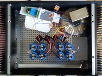
2nd picture shows the PSU: Eight cheap 24Vdc 5 A SMPS (one of them already disassembled, gnd isolated from PE and tweaked to obtain 30 Vdc), four per channel to be connected in series with the ground tap between the 2nd and the 3rd. This arrangement costs less than half of these Connex units (€ 9.95/ea).
Still have to try if it works, but I'm confident, as I successfully did something comparable with four other cheap SMPS units.
Best regards!
My Q-Watt project still sticks in this state 🙄.
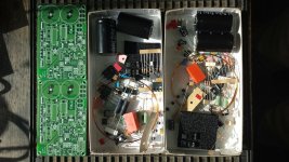
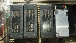
2nd pic shows my PSU, consisting of eight cheap (€ 9.95/ea) SMPS (24 Vdc 5 A). Four of them to be connected in series and tapped for ground between the 2nd and the 3rd one. The rightmost is yet disassembled, tweaked to obtain 30 Vdc and isolated from PE (which will be connected to each aluminum shielding externally). This arrangement costs me less than half of the Connex units.
Still have to try if it works, but I'm confident as I successfully did something comparable with other cheap SMPS.
Best regards!
Attachments
Wow. That's a new approach (at least to me). So you get 30V + 24V = 54V across each pair of SMPS blocks? Please let us know how you get on! Pops....eight cheap (€ 9.95/ea) SMPS (24 Vdc 5 A). Four of them to be connected in series and tapped for ground between the 2nd and the 3rd one. The rightmost is yet disassembled, tweaked to obtain 30 Vdc and isolated from PE...
2nd pic shows my PSU, consisting of eight cheap (€ 9.95/ea) SMPS (24 Vdc 5 A). Four of them to be connected in series and tapped for ground between the 2nd and the 3rd one. The rightmost is yet disassembled, tweaked to obtain 30 Vdc and isolated from PE (which will be connected to each aluminum shielding externally). This arrangement costs me less than half of the Connex units.
Still have to try if it works, but I'm confident as I successfully did something comparable with other cheap SMPS.
Interesting !
Can you elaborate on on the 'tweaks' you did on those SMPS's?
As for your configuration, you are doing this:
+
30
-
+
24
-
GND
+
30
-
+
24
-
Giving you a double 54 volts supply / 5A?
How clean are those SMPS's?
Seems like a good way to get +-54Vdc and gets a 24Vdc supply to run auxiliaries, etc.
Have a look at using RCRC after the smps to clean up the high frequency rubbish that will get past the on board filtering.
Maybe replace one or both of those R to an L+R using a fairly thin wire to increase the R part and help with damping of the inductance.
Have a look at using RCRC after the smps to clean up the high frequency rubbish that will get past the on board filtering.
Maybe replace one or both of those R to an L+R using a fairly thin wire to increase the R part and help with damping of the inductance.
No, I'll tweak each one to give 30 Vdc, i.e. 60V per rail. Yes, I'll dare it 😀. If I'd be eager to 54V rails, I'd adjust the units to 27V each. Besides this, your assumption is correct.
First step is to open the plastic enclosure, using a hand saw. That sounds brutal, but there's really no other way. Next remove the aluminum shielding. Then trace back from the output terminals, peel off the silicone blob covering the relevant components, identify the error amplifier (U3, a TEA1761 in this case which also is a synchronous rectifier controller), it's reference voltage (2.5V) and the output voltage divider with it's tap connected to U3's pin 6. We have to look now at the divider's bottom resistor (R31, marked »4531« and marked by me by two black dots, see pic). If we want to increase the output voltage from 24 to 30V, i.e. by 25%, we have either to increase the current through the divider also by 25%. This is done by decreasing the bottom resistor, either by paralleling it by another one with four times it's value (about 18k in this case) or by replacing it by one of 4/5 it's value. Or we could increase the top resistor accordingly instead, i.e. from 12k5 to 15k3. I still have to decide which way I'll go. Most probably it is much easier to solder a second SMT resistor on top of the existing one at the bottom.
Best regards!
Attachments
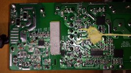
I have to stand corrected: The existing top resistor's value actually is 40k5. To achieve 30 Vdc instead of 24 V, it has to be increased to 49k5. If standard 47k were used, the output voltage were 28.5 V. Might be enough, though. Sorry for the confusion!
Use 51k and pad it down till you reach your required output voltage. This would be in the Meg-ohms range
So maybe start with 56k and pad that down.
So maybe start with 56k and pad that down.
Delange, some advise when you can please.
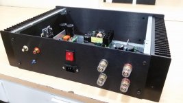
I'm almost ready, wiring nearly complete except the mains socket, mains switch and the mains cabling to the SMPS boards.
So for when i wish to begin the 'Q-Watt on test run', as described in the Elektor article, can you please advise of any precautions?
Thanks
I'm almost ready, wiring nearly complete except the mains socket, mains switch and the mains cabling to the SMPS boards.
So for when i wish to begin the 'Q-Watt on test run', as described in the Elektor article, can you please advise of any precautions?
Thanks
Delange, some advise when you can please.
I'm almost ready, wiring nearly complete except the mains socket, mains switch and the mains cabling to the SMPS boards.
So for when i wish to begin the 'Q-Watt on test run', as described in the Elektor article, can you please advise of any precautions?
Thanks
Just make sure that P1 is fully turned to the left and that you have the power resistors fitted instead of the fuses. Of course, at this time there are no speakers connected. And short the input.
Read the instructions carefully before initial start up so that you understand the process very well.
After this, you're good to go.
EDIT: and carefully check your wiring before start up.
Thanks Delange, ill certainly double check everything and do what you mentioned.
Ill post tomorrow the final images of the amp (before the smoke enamates) that shows the wiring, bar the mains connections.
Once its all up and working ill fit the front led and you mention in an earlier post.
Ill post tomorrow the final images of the amp (before the smoke enamates) that shows the wiring, bar the mains connections.
Once its all up and working ill fit the front led and you mention in an earlier post.
Hey Calpe good luck.
I have a quick question: what insulator is best between the semiconductors and the main heatsink? Is the stuff shipped by Elektor sufficient? What about for the small aluminium heatsink - are you guys using insulating pads? Which product do you recommend?
I have a quick question: what insulator is best between the semiconductors and the main heatsink? Is the stuff shipped by Elektor sufficient? What about for the small aluminium heatsink - are you guys using insulating pads? Which product do you recommend?
Last edited:
I have a quick question: what insulator is best between the semiconductors and the main heatsink? Is the stuff shipped by Elektor sufficient? What about for the small aluminium heatsink - are you guys using insulating pads? Which product do you recommend?
The idea of an insulator is to electrically isolate the component from the heatsink. But at the same time, it should be a very good heat conductor so that the component is able to "discharge" its heat to the heatsink.
The insulators that came with the Elektor kit are ok in both regards. I used them as well and I would advice you to use those too.
For the small heatsink I don't use insulation pads since there is only one components mounted to the heatsink. However, you should be careful mounting the heatsink so that it does not touch any component on the PCB. I have used a bit of kapton tape on the bottom side (next to the output coil) to make sure it is electrically insulated. I also made sure that the heatsink is sitting about 2 mm above the PCB.
- Home
- Amplifiers
- Chip Amps
- My Q-Watt project