Minoten,
Did you catch my post to you here on page 13? (amazing how big this thread is getting)
Anyway, just a few questions I had for you.
What is your throw distance by the way?
Did you catch my post to you here on page 13? (amazing how big this thread is getting)
Anyway, just a few questions I had for you.
What is your throw distance by the way?
Inkog,
Sorry for not seeing the obvious. You are right. I have been thinking parabolic for a long time and this is one of the reasons because of the wasted light.
The real problem as I see it is that the elements are so large that the actual surface of where the light is emitted is no where near the focal point of the reflector. Also unless the element lets the reflected light pass through it much of the light consumes itself.
Hezz
spherical reflector with large arc
I think you should try making a drawing of a 24 mm arc with the center of the arc at the center of a spherical reflector. Light from the center of the arc gets reflected right back through the center of the arc. But look at what happens to the light from one end of the arc: At the very worst case, it gets reflected by the center of the spherical reflector and then travels through the opposite end of the lamp arc. So it will then follow one of the paths taken by light that came directly from that end of the arc!
So I don't think a spherical reflector makes a lamp arc appear to be any larger, unless you move the lamp closer to the focal point at half the radius distance from the reflector.
Guy,
Correct me if I am wrong but in a MH bulb the arc is just there to get the plasma ignited. The actual light comes from the metal halide plasma which expands to fill the entire element container. This being the case as I understand it the light emitting source is not like a tungsten wire or halogen bulb with wire and gas. The light comes off the surface of the element shape which is usually spherical for small bulbs and cylindrical with with rounded ends for larger wattages.
If this is the case the arc gap or geometry is not as important as the plasma container as the entire surface of the plasma container gives off the light.
Hezz
light emission
I have actually looked at the arc in my lamp (using welder's goggles) and also at the image of the arc projected by the fresnels onto a piece of paper. It looks like the light is emitted pretty evenly from the entire volume of the plasma container.
The initial high voltage sparks (the "pulse" in a pulse-start lamp) produced by the ballast ionize the gas between the electrodes. Once a path of ionized gas molecules is there, a lot of current can flow between the electrodes. This heats up all the gas in there until it reaches a high enough temperature to become a plasma: A nucleus and electron "soup" that emits photons to get to a lower energy state. Since the current keeps on flowing, the plasma reaches an equilibrium (temperature stability) where the energy output in photons = the energy input as electrical current.
Anyway, my point is that the light comes from the entire volume of plasma, not just the surface where it touches the glass. In fact, I bet the glass cools the plasma so much that it doesn't emit much light near the surface.
Guy,
thanks for your input. Unfortunately this complicates things even more than I thought but it makes sense that the entire volume would be emitting light.
Inkog,
Looks good. I'm amazed at how good your plans are from just basic graphics software.
Hezz
thanks for your input. Unfortunately this complicates things even more than I thought but it makes sense that the entire volume would be emitting light.
Inkog,
Looks good. I'm amazed at how good your plans are from just basic graphics software.
Hezz
Inkog,
I was just reading up higher in the thread and read how you had heard that some guys using the 330 mm FL fresnel combination with the 135 mm lens are having light problems. You should know that even though Allen states that the 330 mm FL field fresnel will work with the 135 x 450 mm lens it is not ideal. I believe Allen stated this because he did not yet have any appropriately sized fresnels for that lens and did not want to send customers to a competitor.
These were the fresnels that Allen was originally selling for his 80mm x 327 mm FL cemented triplet. Not only does the 135 mm air spaced triplet have a longer focul length but is also has a larger aperture so it can capture more light. For this reason it needs a significantly longer FL field fresnel to perform at it's best.
The field fresnel needs to have a longer FL than the objective lens usually. The ideal FL of the field fresnel depends on your through distance since this changes the objective lens to LCD focus distance. And also the FOV of the lens. But for most of us the field fresnel with a 550 - 650 FL will be the best for that lens. And the 650 mm FL fresnel should be better if you want your image of 120 inches or larger since the larger your projected image is the further the lens will be from the LCD when it is in focus.
The longer the FL of the field lens ( up to the point where it is too long that it wastes light output) the better as the light angle going through the LCD is not as steep.
Hezz
Hezz said:Inkog,
since the larger your projected image is the further the lens will be from the LCD when it is in focus.
Hezz
this is not that way, is the other way. larger image, closer the lens from the lcd.
my good friend diyeitor has a projector with 330/330 fresnells and larger focal triplet than 450. well, just look at his projections.
i know larger focal fileld fresnlell is ideal but when you have no way, you can find solutions geting the lamp closer to the rear fresnell.
Rox,
I have measured the DIY 135mm lens distances and you are emphatically wrong. Now if you mean using a lens with a shorter FL then yes you are correct. But for the same lens what I said holds true at least for this lens.
Now, if you are still interested in the DIYprojectorcompany 135 mm x 450 mm FL lens FOV then you can post a message to either DIYprojector company or to DIYbuildergroup and see if they know it because they both sell that lens.
My experiments leave me to believe that the lens will work with no problems with 17 inch and even a 19 inch LCD. I don't have the exact FOV for this lens. You are going to have to do your own homework on this if you have to have this information.
Now if this does not satisfy you or you don't have the money to buy it you can try making your own even higher quality triplet that I designed. It is back in the old archived threads under something like DIY high end triplet. It has a fully corrected 40 degree field of view. You could grind the lenses yourself by hand and it would take a long time but you could have an awesome lens. There is enough information there to build the whole lens system. We got a quote from India to have the lens manufactured in small quanties of 100 - 200 lenses. The cheapest was around 600 USD. For American companies it is over 1200 USD for small quantities.
There is no cheaper large format triplet offered anywhere unless you happen to find a surplus one for little money. But this is unlikely as DIY projector builders have been scavenging the internet for two or three years buying up any and all available similar products. I would be willing to bet that if these 135 mm lenses where only available on e-bay they would be going for more than we are paying for them.
The other alternative is to find an old over head projector and scavange the lens system off from it. You would then need to go with a 15 inch or smaller LCD for most OHP lenses.
But, check out Crusers 17 inch SGI project. He found a OHP lens that worked with a 17 inch LCD quite well. He gives the model name and number on the DIYbuildergroups web site and also in the thread in this forum.
Hezz
2meters throw, needs 58cm lcd-triplet distance.
3meters throw, needs 52,9cm lcd-triplet distance.
4meters throw, needs 50,7cm lcd-triplet distance.
5meters throw, needs 49,4cm lcd-triplet distance.
larger image size = larger throw = closer lcd-triplet distance.
do you want to know the maths behind it?
and yes, i am still interested on the FIELD ANGLE this lens have, but no replys to me from those two sellers. I think they are bad news so don´t like to be known. (only a suposition)
Rox,
It is likely that the 135mm x 450 mm FL lens has some significant compromises otherwise it would'nt be so affordable. It may for this reason that they don't post the FOV.
Anyway lenses that I know to work or are said to work for 17 ich LCD are the following which are available in the DIY community.
1) The OHP lens that Cruser used on hisSGI 17 inch high res projector. Check the thread to find out the model number.
2) The DIYprojector company 135mm x 450 mm FL triplet was tested by me and Allen with a 17 inch LCD mockup and showed good edge to edge resolution. With my test using no fresnel lens. I have not yet seen a projector built using this lens with a 17 inch LCD.
3) The LumenLabs Pro triplet is said to work with a 17 inch LCD and I have seen one finished design with that lens and a 17 inch LCD.
I don't know the FOV for any of these lenses.
Hezz
2) The DIYprojector company 135mm x 450 mm FL triplet was tested by me and Allen with a 17 inch LCD mockup and showed good edge to edge resolution. With my test using no fresnel lens.
Care to share a little more about your setup? I am having a hard time getting a 15.4" source to fully focus, I was thinking about eliminating the whole front fresnel also.
yes hezz, show us the setup you used without fresnells is ok since it says ther eis no problem with the light path (field fresnell focal lengh does not care this way)
tell us your throw on this setup.
anyway the light you could have collect and project was enought to check the corners?. Most people say they can see all the image source "corner to corner" but the goal is to see it focused.
i checked allens (astaples) setup on the test he says he did and has no sense for me. His 5,5" light source---fresnell distance has no sense at all since it would be diverging on the side of the triplet, it never would work.
Ok guys,
I will explain what I did and first off let me be realistic. In my test which was with a 12 - 13 foot throw distance I got about a 15.5 inch LCD to lens distance on the longer threaded end of the triplet. The lens is not perfectly symetrical so the LCD to lens distance is a little different depending on which way you orient the lens. The other way had a little closer LCd to lens distance and threw a little larger picture. Usually for a chromatically corrected lens one orientation is better as one end of the lens is designed to image the small original image. I tried both methods and could not tell a difference in quality with my crude setup.
Here is Brainchilds setup using the same lens. With a 15 foot throw distance he gets a somewhat longer LCD to lens distance and he needs a little longer field fresnel then what I need.
Attachments
Ok,
The way I tested my lens was with a 17 inch test paper that I printed on my inkjet printer. I tiled the picture together and made it an 4:3 aspect ratio picture.
I had a small portable light table that I made for viewing slides and tracing pictures. The light table is nothing more than a frame of 1 x 4 wood about 18 x 14 inches in size. It has a 15 to 25 watt small flourescent bulb inside and the bottom is lined with tin foil. The top is a 1/4 inch thick piece of white acylic plastic. There is no reflector other than the loosely laid tin foil in the bottom and sides. It is not real brite so I had to turn off all of the lights to see a good image.
I set the light table up on it's side on a card table and some boxes so that it's light emitting side was towards the wall. I then taped the picture on the light table. I then held up the lens with my hand until I got a focused image.
Results: The overall focus and brightness was better than when I tested a 15 inch mockup with the DIYprojectorcompany 80 mm triplet using the same light table and the same throw distance.
To be honest, the edges were not as bright and perfectly focused as the center but it was still good and better than the 80 mm lens had been with a 15 inch mockup.
I expected that the edges would be less bright because of the light table method which does not have an even light on the whole image. Also I could not hold the lens in perfect alignment by hand. Even so I was impressed that the lens would work well with proper alignment and holding and a good light engine. The image edges were well defined at all edges and the lens was focusing stray light at least for another inch around the outside of the test image which leads me to believe that this lens will work with a 19 inch LCD.
Here is Allens 17 inch test image. I recall that he was using a old OHP light engine for this test so it may have had a longer FL than his 330 fresnels. That could explain why his image is good edge to edge.
No if you get really critical it looks like the edges are not quite as good as the center of the image but it is still good enough to not cause any significant issues.
In all likelihood the lens is not corrected out to a wide FOV because that is more expensive to make.
Hezz
Attachments
Now,
Some of the guys think that this is the 135 mm lens. This picture is from Highland or Highlight optics or some company like that. It's been to long and I don't remember the exact name but you can look it up in the archives.
If this is a picture of how the lens is built I can tell right now that it is a lens with significant compromises which make it less expensive to manufacture. I can tell you that it is possible that our 135 mm lens is built like this one. Notice that the first and last lenses are nearly identical. This makes the lens less expensive to make and the same molds or grinding program can be used to make the first and last lens.
I modeled a lens like this in optical software and it has significant compromises. Meaning that it is only chromatically corrected within a fairly narrow field of view. This means that areas outside the FOV will have less resolution.
Hezz
Attachments
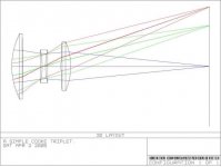
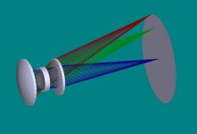
Now here is a fully computer optimized 40 degree angle FOV cooke triplet that I optimized in software. You will notice several things. Some are not so obvious and some are. First all of the lenses are different shapes and geometry. There are no two surfaces or spaces that are the same. Even the surfaces that appear nearly flat on the first and third lens are very small but absolutely necessary convex surfaces.
The smaller end must, and I repeat must be oriented towards the smaller (LCD) image for this lens to work properly. The other way will have severly reduced light output and resolution. Changing any parameter in this lens system even slightly has a drastic effect on lowering the quality of the lens.
Hezz
Attachments
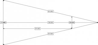
Ok,
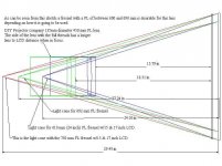
I don't know if you can make out this diagram of mine which I did to help me decide on a fresnel FL size for my application. Also I believe I was wrong in my statement above. I think the LCD to lens distance was more like 18 inches for my 12 - 13 foot throw distance at the orientation I wanted to use.
Hezz
Attachments
- Status
- Not open for further replies.
- Home
- General Interest
- Everything Else
- The Moving Image
- DIY Projectors
- My ProView 15.4" 1280x800 HD project...