Yes, I agree with you. 🙂It's very difficult not to have mains hum. But what you need to do for the challenging target is simple. Make your PCB an isolated island. In other words, no conductor from your PCB is preferable as possible as you can. Power rail must be a battery for isolation from the earth ground. From battery to your PCB is a conductor but no current path to the earth ground keeps the principle, isolated island. Captured data from ADC board to PC is through an optical interface, where conductor entirely doesn't exist. Both isolations can guarantee no interference of mains hum.
You can find a slight footprint of mains hum at the 3rd pic. of post #1, which is the plot of made in china board(ES9038) powered by mains. 50Hz and 150Hz are visible in the blue plot. My DIYed PCBs are powered by batteries, where almost no mains hum exists.
I'm impressed with no viable mains hum on a FFT noise floor of -160dB 🙂
The best we can achieve with the R&S UPD's in the lab is about -145dB. TBH, I dont really worry about these components, your always going to have them in the system and you know their cause (they are not due to modulator issue etc.)....
If you look closely at the DevDAC II PCB we are working on, you can see a pair of pin headers below the Clock circuit and between the transformers (One header is in the isolated analogue domain, and the second is in the "dirty" digital domain)- these will interface to an ADC board mounted above - the ADC board uses a pair of PCM4202 interfaced to the FPGA via only the SDM outputs so we can archive Vinyl etc in native DSD.
Discrete DAC Stg6.png
The PCM4202 are still the best sounding ADC's we are aware of that have a true 1bit SDM output (not a faked 1bit output re-modulated / decimated from a multibit SDM).
The trouble with the PCM4202's is that they have a 'high' NF at about -140 to -145dB... perfectly adequate for Audio, but not for measurement...
We will have a look at the AD part for a test system, we have been planning for a long time now to update the UPD's internal ADC board.
Last edited:
why you need high power cpu
My DSM is always hardware one by FPGA because I don't have enough software knowledge to write code for DSM. As long as I know, the theoretical background of DSM was already fixed by many researchers. They are available in the book, "Understanding Delta-Sigma Data Converter, Richard Schreier and Gabor C. Temes, Wiley-IEEE Press, 2004." I'm sure this is the best summary.
PlayPcmWin / Wiki / PCMtoSDM
I guess the ADSM7-512 by HQplayer is a cousin of 7th order CRFB. 7th order has two extra integrator stages over 5th order(figure.8). Even if the implementation is done by software, the basic architecture of DSM is the same. My question is why HQplayer requires high processing power to calculate the formula. Large floating-point values(128?) and high OSR(x512) could be the reason. But recent high power CPUs could easily do the job. Even a small FPGA(xc6slx9) can output 5th order with no local feedback(g0=g1=0) in 512OSR(40bit resolution) on the fly. The calculation is an integer value; of course, you have the same result.
My noDAC is NRZ, where the difference between low to high transition and high to low is very critical. High OSR degrades the performance. 64OSR or 128OSR is an optimum solution. It's better to use high order DSM(8th or 9th) to utilize 64OSR. You need to push away quantization noise above the audio band. Low OSR with high DSM order is the best combination for my noDAC. I mean an optimum DSM architecture depends on your DAC topology.
As JohnW mentioned: simple use Notch (best active one with low THD & noise contribution & level loss 🙂)
The point is this: If you drive the DAC with large levels, you get the THD from both DAC & ADC 😀
In other words, if your Notch lowers the 1kHz ADC level by -50dB, you will drive the ADC also on a more THD less range. So you would see the real THD pars of your DAC 😀
Hp
Yes, it's true. 🙂A quality notch filter is one solution to know precise numbers. But I need to know real DAC performance. NoDAC has the best performance at -0.1dBFS. I want to know the performance at -0.1dBFS, though it may degrade ADC performance.
Yes, it's true. 🙂A quality notch filter is one solution to know precise numbers. But I need to know real DAC performance. NoDAC has the best performance at -0.1dBFS. I want to know the performance at -0.1dBFS, though it may degrade ADC performance.
With a notch you still measure real DAC performance, your just not stressing the ADC's "Real performance" as it no longer has to function with a Full Scale input signal.
Our R&S UPD's we use in the lab use a very old ADC from Crystal semiconductors with barely 18bit performance, but uses a simple 36dB or so tracking notch filter to increase the measurement dynamic range with single tone stimuli..
I'm wondering how much of the granted, already very low THD you measure is ADC related? - A tracking notch would expand your ADC's spurie free measurement range.
Last edited:
With a notch you still measure real DAC performance, your just not stressing the ADC's "Real performance" as it no longer has to function with a Full Scale signal.
Thanks for correcting me.🙂 I had a misunderstanding about the function of a notch. Do you have a recommendation about quality notch? I know 4.9MHz sampling has less THD than 4.1MHz. Large amplitude fundamental may be the reason.😱
Thanks for correcting me.🙂 I had a misunderstanding about the function of a notch. Do you have a recommendation about quality notch? I know 4.9MHz sampling has less THD than 4.1MHz. Large amplitude fundamental may be the reason.😱
Jarek who works with me designed a quite complex tracking notch, but I've seen simpler fix frequency ones around the internet, you only need to null by say -20dB to give state-of-the-art performance from your already VERY good ADC.
Yes, digital crossover is the best objectively. I find HQPlayer and the work put into it interesting, but ultimately I don't see the point of turning PCM into something else in an attempt to bypass parts of the DAC IC data path. There is nothing deficient about the 96 kHz or even 44.1 kHz PCM performance of modern DACs. I don't think these claims of audible superiority of ridiculous DSD rates would stand up to blind testing.
Well, maybe nobody claims pcm sounds bad, but there are certain technical deficiencies in a certain data path as well as there's other ways to Rome.
I don't see dsd vs pcm as a better versus worst discussion per se, but when one learns and tries to know about them and tries to comprehend the underlying structures a few things can be said about them and trying to make them better is the least any curious technical audiofool would be interested in.
Pcm in converters is a dead horse and the industry needs niches to explore all ways to make the best of new technologies. Also: hqplayer isn't just for dsd, there's plenty for pcm as well (maybe even more, dunno?).
What, to me, is most important for converters is the same as for speakers: they needn't be bad as they are, but not having under control (being able to tweak) main aspects of a converter (or letting go of being able to control things we couldn't before) is just a weak thing to begin with. In speakers that's e.g. optimized frequency response and range as well as room optimisation, for da converters that's obviously the algorithm and filter techniques, because those are new and might be per surroundings different. This means:
They might matter to you but that's not what a company might be interested in (or will offer you). They care about volume mostly, that's hardly good for me but good for comparison.
Btw. All dacs suffer mostly from its surroundings, no matter what format, i've heard bad dsd and bad pcm but mostly I like the tinkering and building of know how by it🙂
Well, maybe nobody claims pcm sounds bad
When compared to native DSD - I'll say PCM sounds worst in direct A/B comparison!
Note I said NATIVE DSD, there is no point in DSD if its just a remodulated PCM. Once PCM has been involved in a signal path, its all over for true HiFi performance.
Note I said NATIVE DSD, there is no point in DSD if its just a remodulated PCM. Once PCM has been involved in a signal path, its all over for true HiFi performance.
That seems rather a bold claim to me, but perhaps I am missing something. From my own experience ripped SACD at DSD64 sounds worse than well recorded CD audio converted to DSD512 (as well as it can be done with HQ Player). However, at the moment I am doing the subjective comparisons using AK4499 eval board (very carefully 'surrounded') which may unduly influence the result.
EDIT: Sorry for continuing off-topic, but some of the issues that arise along the way seem to require further illumination. Hopefully, this can be wrapped up shortly.
Last edited:
That seems rather a bold claim to me, but perhaps I am missing something. From my own experience ripped SACD at DSD64 sounds worse than well recorded CD audio converted to DSD512 (as well as it can be done with HQ Player). However, at the moment I am doing the subjective comparisons using AK4499 eval board (very carefully 'surrounded') which may unduly influence the result.
EDIT: Sorry for continuing off-topic, but some of the issues that arise along the way seem to require further illumination. Hopefully, this can be wrapped up shortly.
I was careful to say Native DSD, almost EVERY SACD I have been able to analyse is a PCM remodulation, typically you can see 48KHz based spuire from the original mixes etc. Sadly SACD was abused... there is no point in DSD once there has been conversion to PCM. I've watched DSD recordings being produced from 384KHz PCM as there are few editing / mixing tools to allow true DSD studio "Production".
DSD only really works from Analogue master tape / analogue mixing desks, live events (from analogue mixing desks)... DSD also make sense when archiving Master tape and vinyl.
Another problem is that there are very few Native ADC's or DACs, again they remodulate (such as the AKM ADC's or ESS DAC's etc).
When people comment poorly about DSD, dig deeper and you will find they have not heard true native DSD, (either due to recordings or non native DAC converters etc)...
When we work on designing digital filters for PCM decimation in the lab, our reference is always the native SDM source, the trouble is I've NEVER heard a Filter that does not take something away from the original SDM source - generally the slower = poorer attenuation the filter, then the better they tend to sound (Pre ringing is very important here)... One of the reasons I'm an early support of MQA is that they are trying to bridge the difference between PCM and DSD even if they don't say it in so many words... HDCD was also very clever - which MQA has many parallels with.
Notice the latest move to include slow filter roll-off options with all of today's DAC's.
Last edited:
Thanks for correcting me.🙂 I had a misunderstanding about the function of a notch. Do you have a recommendation about quality notch? I know 4.9MHz sampling has less THD than 4.1MHz. Large amplitude fundamental may be the reason.😱
Search for Twin T or Fliege notch filters:-
Fliege High Speed Notch.pdf
There are values for 10KHz notch (lowest on the table), just use a decade higher component values for a 1KHz notch.
I've used Twin T notch filters in the past with good results (as used in AP, HP and R&S etc)
You don't need a deep notch, 20dB will be fine - just one with high Q.
Last edited:
When people comment poorly about DSD, dig deeper and you will find they have not heard true native DSD, (either due to recordings or non native DAC converters etc)...
When we work on designing digital filters for PCM decimation in the lab, our reference is always the native SDM source, the trouble is I've NEVER heard a Filter that does not take something away from the original SDM source - generally the slower = poorer attenuation the filter, then the better they tend to sound (Pre ringing is very important here)... One of the reasons I'm an early support of MQA is that they are trying to bridge the difference between PCM and DSD even if they don't say it in so many words... HDCD was also very clever - which MQA has many parallels with.
Notice the latest move to include slow filter roll-off options with all of today's DAC's.
That only shows that slow filters are in fashion nowadays, not that they are better or worse than steep filters. The audio industry is sensitive to fashion. For example, in the 1980's, phase linear reconstruction filters were generally preferred over minimum-phase filters, nowadays it's the other way around.
In any case, it seems illogical to me to worry about ultrasonic pre-ringing, yet prefer a recording format with lots of ultrasonic quantization noise - why would one ultrasonic artefact be a problem and another one not?
I'd not call it fashion, I'm a consultant designer for a few Audio IC manufacturers and recommend atleast less aggressive filters based on experience from my own commercial DAC designs
One of these designs, the Audiolab MDAC has sold over 70K units and almost universally our custom coefficient "Optimal transient filter" is overwhelmingly preferred by the MDAC owners I've spoken with.
These custom Optimal Transient filters have no Pre or Post ringing - this to me is pretty much proof that ringing in the time domain is detrimental to sound quality (where as all the other MDAC filters types have Pre / Post ringing to varying degrees).
We also implemented an "optimal transient" filter on the little ProJect S2 Prebox DAC with much the same preference ratio with customers, so feedback its not limited to just one design platform.
MDAC - optimal transient filter (Time domain):-
Optimal Transiant Custom.jpg
Compare the time domain to the typical Fast FIR (ESS standard Fast FIR):-
Fast FIR.jpg
I'm glad that more attention is being paid by IC manufactures to the time domain over frequency domain performance of digital filters - "Ideal" Fast type FIR digital filters tend to sound really poor in my experience.
Last edited:
Do you listen to impulses? What do you think the fastest signal you can legally have in a band-limited audio system is? It is fashion, sampling theorem tells us all we need to know.
DSD is utterly pointless. Data acquisition is a big business in all industries. DSD was created to serve Sony's commercial interests only. Why do you think it is that no other DAQ systems use such a scheme? It has no advantages in a world of multi-bit converters.
DSD is utterly pointless. Data acquisition is a big business in all industries. DSD was created to serve Sony's commercial interests only. Why do you think it is that no other DAQ systems use such a scheme? It has no advantages in a world of multi-bit converters.
Last edited:
One could take a pc or fpga and program it so it benefits frequency domain more than phase domain and vice versa.
What you'll hear when e.g. playing an acoustic guitair is that the timing of the harmonic structure changes when switching between those options, as an example: the higher part of the harmonics seem to arrive louder and earlier (in short: are more pronounced, seem brighter) than the other filter method, or the other way around: more integrated, or in comparison darker. This also changes the imaging to being closer or further away.
It's imaginable this effect depends on the adc (topology and software settings) used at the time of recording as well as your dac chip used, and the type of filtering and phase of the speaker as well, but that's too much for now.
Are those differences there because there's some ultrasonic change which doesn't find it's way back in the audible range then what can be the cause of this effect?
I keep on thinking this: if one needs e.g. 120dB of resolution and that filtering is the solution for Shannon to be right about sampling theory and reconstructing the digitized waveform is the goal, then it's pretty logical to conclude that pre and post ringing can be a major contributor to perceived sound quality, or at least to differences.
By changing the place and the amount of this ultra sonic ringing, when it gets integrated by the analog filter later, it must result in a difference between what was recorded and what now comes out.
Btw.With dsd the ultrasonic noise is barely (not?) correlated with the music signal, the filtering is so it should have a bigger effect.
You do know the time and frequency domains are related?
The ideal filter is a brickwall. Do you know what the impulse response of that looks like? It's a sinc.
Which looks more like the ideal filter... the sharp FIR, or the trendy (poor) filter?
Anyway, this all has been covered before and it's not really on topic so I'll stop derailing the thread 🙂.
The ideal filter is a brickwall. Do you know what the impulse response of that looks like? It's a sinc.
Which looks more like the ideal filter... the sharp FIR, or the trendy (poor) filter?
Anyway, this all has been covered before and it's not really on topic so I'll stop derailing the thread 🙂.
Do you listen to impulses? What do you think the fastest signal you can legally have in a band-limited audio system is? It is fashion, sampling theorem tells us all we need to know.
DSD is utterly pointless. Data acquisition is a big business in all industries. DSD was created to serve Sony's commercial interests only. Why do you think it is that no other DAQ systems use such a scheme? It has no advantages in a world of multi-bit converters.
Well everyones entitled to there own opinion - DSD is nothing but SDM, when I refer to DSD I guess I should be more clear and say 1bit SDM (rather then Sonys marketing).
No, we don't listen to impulses (just as we don't listen to pure sign waves), but over the years I've found that optimizing time domain performance is more indicative of perceived audio sound quality then frequency domain measurements.
I can design DAC's / systems with stupidly low THD and ultra flat frequency response, but at the end of the day these measurements have little baring on the final sound quality, however its my experience that a design where effort has been taken with the time domain has a much closer baring to the results of the listening tests.
I've come to respect that the time domain is more important then the typical frequency domain / THD measurements the audio industry focuses on...
For many years now it should be apparent that our standard audio measurements have little relevance to real life listening experiences (on the assumption they are adequate - not some crazy high THD etc.) - so its time we faced the facts and start looking elsewhere... Obviously the time domain is nothing new, but as audio designers we have not traditionally focused on optimizing the Time domain.
Each to there own 🙂 I now put much greater focus on the time domain performance of our designs 🙂 and in digital, its an area where well designed SDM wins hands down over PCM.
Last edited:
You do know the time and frequency domains are related?
The ideal filter is a brickwall. Do you know what the impulse response of that looks like? It's a sinc.
Which looks more like the ideal filter... the sharp FIR, or the trendy (poor) filter?
Anyway, this all has been covered before and it's not really on topic so I'll stop derailing the thread 🙂.
Chris, you should maybe reread the thread with the knowledge that this and the page or two before, apply to pcm just the same.
In addition to that, I would like to point out that the overwhelming majority of current dac and adc chips manufactured are purely sdm based, but TI still has some that mix sdm with pcm.
Either way, it couldn't reach the quality without sdm inside any of those.
I love the pcm63 and some other true ladder dac's, but they're impossible to get a hold on nowadays.
In another thread I'd love to engage in settling time versus amplitude resolution discussions, or about the best way to load the current output of the chip but for now, this sdm thingy is just great state of the art ramblings, sharing of curiosity and enthusiasm, gone off topic every once and a while, of a great thread started by xx3stksm's excellent work.
This should all be in good spirits.
I'm sure the brick wall filter isn't a culprit because the digital system is ultimately band-limited one. The brick-wall inevitably outputs ringing to do their job if the input has out of band spectrum. If the input square wave is properly band-limited, the brick-wall never outputs ringing. The 1st pic is the evidence. The upper waveform is the "legal" squarewave, which has three spectrums 6kHz,18kHz, and 30kHz in 96kHz sampling. The lower one is the output of the brick-wall with 40kHz cutoff. The three spectrums are in the passband, where neither amplitude nor phase is changed. The lower is the same as the upper. The real culprit of ringing is the out-of-band spectrum, not the brick wall.
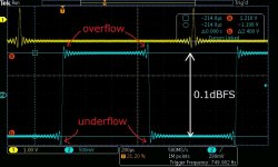
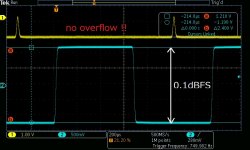
But I guess recent loudness war files make the brick wall faulty. The 2nd pic is 0.1dBFS squarewave. Loudness war files have almost the same effect. If you don't have 3dB headroom, nearly every recent CD has Inter Sample Overs. Overflows and underflows cause fatal degradation in SQ. If your reconstruction filter is ringingless like the 3rd pic, no overflow exists even if you don't have 3dB headroom. The disadvantage of ringing less filter is slight droop.
I'm sure -3db droop at 20kHz(typical performance of ringingless filter) is far more acceptable than overflow. I guess that's the reason why ringingless or slow one has a popularity.
Attachments
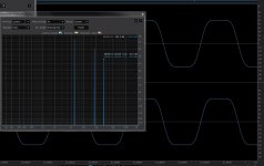

I'm sure the brick wall filter isn't a culprit because the digital system is ultimately band-limited one. The brick-wall inevitably outputs ringing to do their job if the input has out of band spectrum. If the input square wave is properly band-limited, the brick-wall never outputs ringing. The 1st pic is the evidence. The upper waveform is the "legal" squarewave, which has three spectrums 6kHz,18kHz, and 30kHz in 96kHz sampling. The lower one is the output of the brick-wall with 40kHz cutoff. The three spectrums are in the passband, where neither amplitude nor phase is changed. The lower is the same as the upper. The real culprit of ringing is the out-of-band spectrum, not the brick wall.
But I guess recent loudness war files make the brick wall faulty. The 2nd pic is 0.1dBFS squarewave. Loudness war files have almost the same effect. If you don't have 3dB headroom, nearly every recent CD has Inter Sample Overs. Overflows and underflows cause fatal degradation in SQ. If your reconstruction filter is ringingless like the 3rd pic, no overflow exists even if you don't have 3dB headroom. The disadvantage of ringing less filter is slight droop.
I'm sure -3db droop at 20kHz(typical performance of ringingless filter) is far more acceptable than overflow. I guess that's the reason why ringingless or slow one has a popularity.
Exactly, you understand perfectly.
mterbekke said:In addition to that, I would like to point out that the overwhelming majority of current dac and adc chips manufactured are purely sdm based, but TI still has some that mix sdm with pcm.
Either way, it couldn't reach the quality without sdm inside any of those.
I love the pcm63 and some other true ladder dac's, but they're impossible to get a hold on nowadays.
No offense, I don't think you fully understand what I was getting at. The modern DS DACs are not 1-bit DSM, they are multi-bit (5-bit, 6-bit, etc.). John's point, which I agree with, was that most of these converters do not have 1-bit direct paths and thus your DSD output still gets processed. Even in a DAC that advertises a Direct DSD mode like CS43198, it just doesn't get filtered, it still gets converted into whatever representation the actual DAC ingests.
DSD makes sense for xx3stksm's project because of the architecture.
- Home
- Source & Line
- Digital Line Level
- My no DAC project, FPGA and transistors