@Calvin: agreed!
I had a fellow villager having a coffee at my place and we listened my stats and comared them to my fast built and cheap OB speakers (consisting of 2 Peerless 12 inch woofers per channel and 1 "full range" 4 inch driver by Mark Audio (Pluvia), but especially with one particular recording there was a huge difference in sound quality between the loudspeakers.
By the way, when just re-installing the newly coated esl, it seemed to have the same sensitivity as the other channel. But tonight I was listening some music and got the impression the newely coated esl sounded louder than the other channel. After a quick measurement I discovered the newly coated panel is 4 dB louder than the other panel. So maybe, if I feel in an active mood, I will service the other channel as well.
Just wondering: do other esl builders here experience differences in sensitivity in their stats, for instance, just after finishing them, and / or after several years? If so, how many dB?
I suggest, do it ASAP! The explored (detected) asymmetry can make a continuous discomfort - partially as placebo effect too.So maybe, if I feel in an active mood, I will service the other channel as well.
Hi all,
almost 4 years have passed and I'm still fully enjoying my fifth pair of DIY stats! The only issue I had was losing sensitifity which I solved by applying another coating on top of the old one. I had to do this for both panels, but not at the same time. As I made the panels easy to service, servicing was an easy task fortunately!
After many experiments with dynamic woofer additions I come to the conclusion that I either dislike dynamic and electrostatic driver combinations, or I am incapable to do a good integration between both. After many listening experiments I always prefer the esl only implementation. I dislike the extra DSP and power amps as well.
There are at least two options to extend LF range for a full range esl and I'm considering one of them for my sixth build: a double diaphragm full range esl, or just the same model as the current one, but about double it's height. The goal is to extend LF without compromising HF. I think the easiest option would be to just double height and half the transformer step up ratio, as raising d/s distance will make the panels less effective (higher bias voltages needed, lower lifespan?)
I remember Calvin writing about building double diaphragm els panels and that this setup would result in extended LF because the fundamental resonance frequency gets lower. I'm not 100% sure about this, for instance, would the resonant frequency be comparable between a double diaphraghm esl and a similar, single diaphragm panel which is double in height compared to the double diaphragm panel?
It will be more complicated to implement a double diaphraghm panel using wire stators, which I prefer, because of electrical segmentation. Any suggestions about those two choises?
Last edited:
One approach to some of the issues is to do double diaphragm only on low-passed bass sections. Then diaphragm-to-diaphragm spacing doesn't have to be so small. Martin Logan used the double diaphragm on bass only technique on the CLX a few years back.
If it's a completely separate diaphragm, you could also try thicker Mylar for the bass section to decrease resonance frequency. I messed around with that, but it was so long ago I don't remember the result off the top of my head. I do remember that I was using 1 mil (25 micron) Mylar.
If it's a completely separate diaphragm, you could also try thicker Mylar for the bass section to decrease resonance frequency. I messed around with that, but it was so long ago I don't remember the result off the top of my head. I do remember that I was using 1 mil (25 micron) Mylar.

The main resonance on a double membrane electrostatic will be higher, not lower, this is easy to track on headphones.I remember Calvin writing about building double diaphragm els panels and that this setup would result in extended LF because the fundamental resonance frequency gets lower. I'm not 100% sure about this, for instance, would the resonant frequency be comparable between a double diaphraghm esl and a similar, single diaphragm panel which is double in height compared to the double diaphragm panel?
The thicker Mylar gives smaller compliance at same mechanical tension. It rises the resonance point, because the moving air mass a lot of bigger than the membrane alone. The additional mass of 25 micron mylar (instead of 12) is neglible at bass panel at basal resonance frequency.If it's a completely separate diaphragm, you could also try thicker Mylar for the bass section to decrease resonance frequency.
My AI friends and the books I have handy suggest that compliance changes related to thickness are not a significant factor affecting fundamental resonance in thin, tensioned membranes. They all include mass, tension, and size/shape though. When prompted for identically sized and tensioned membranes but of different thicknesses, ChatGPT simplified the relationship to this:

The basic relationship agrees with what I'm seeing elsewhere, though the equations are more complex if you want to calculate everything.
When prompted specifically about compliance related to material thickness, Gemini said: "Generally, the effect of increased mass due to thickness increase is more significant than the effect of decreased compliance, leading to a lower resonance frequency for thicker membranes."
Last edited:
The bass panels have a few tenth of m2 radiating surface. The moving air mass is a magnitude bigger than membrane alone: the 12,5 or 25 micron isn't give relevant mass difference. Your aequation is can true at very small surface (not bass panels) or in vacuum, but only when the mechanical tension's definition is N/m. I think, the "mechanical tension" means N/m2. It will same, if we elongate the membrane material with same %, it causes smaller compliance. I took a mistake, when I haven't define the mechanical tension's definition.
I used the term "mechanical tension" as "mechanical stress". I'm medical doctor, and we use the "mechanical tension" term as sinonime of the "mechanical stress" at interpretation of Frank-Laplace law.
As example see Google: "The Laplace law as it pertains to heart function is that the tension, or stress, on the left ventricular wall of the heart is directly proportional to the left ventricular pressure and radius, and is indirectly proportional to two times the thickness of the left ventricular wall."
I apologize, if I was not precise enough.
Hi,
I´m pretty sure that I didn´t say this: "I remember Calvin writing about building double diaphragm els panels and that this setup would result in extended LF because the fundamental resonance frequency gets lower."
The reason utilizing double diaphragms is solely to increase output SPL, not to lower fs.
The increase of up to +6dB in SPL is due to almost doubling the force-per-area.
Fortunately this increase doesn´t work fullrange but follows a lowpass response, depending on the dimensions and distancing of the diaphragms.
With my panels the increase almost cancelled out the drop in amplitude response due to the acoustic short, and at the same reduced the burden on required equing and excursion considerably.
jauu
Calvin
ps. If You build a dipolar tower with dynamic drivers I can almost guarantee you that you can achieve seamless integration of panel and bass-tower.
As plus you can achieve less colouration due to a flatter amplitude response and a massive increase in dynamic range.
Of course the higher effort in remains ... Xover plus amps plus bass-tower.
Hi, thanks for all the responses! Doubling the diaphragm doesn't seem so interesting now.
@mattstat: having a seperate LF diaphragm feels a bit tricky, as I remember from a post from bolsterst that if done wrong one can get ill effects between the mechanically separated panels:
@Calvin: sorry for my incorrect memory!
I still have the line array dynamic dipole towers and will give them another try.
@mattstat: having a seperate LF diaphragm feels a bit tricky, as I remember from a post from bolsterst that if done wrong one can get ill effects between the mechanically separated panels:
Hi bolsert,
sorry for my (very) late reply, I missed it. Thanks again for your extensive and insightful repy. I think I will keep this stat as it is and design and build a new version that hopefully solves the limitations / problems of my current model.
This is a rough picture just to demonstrate my current idea:

(the areas are just an indication, not exact dimensions. The red / blue colored areas constitute the front view of the complete stat, the drawing below is to demonstrate the electrical ladder segmentation)
design decisions:
*...
sorry for my (very) late reply, I missed it. Thanks again for your extensive and insightful repy. I think I will keep this stat as it is and design and build a new version that hopefully solves the limitations / problems of my current model.
This is a rough picture just to demonstrate my current idea:
(the areas are just an indication, not exact dimensions. The red / blue colored areas constitute the front view of the complete stat, the drawing below is to demonstrate the electrical ladder segmentation)
design decisions:
*...
@ silvershadelynx,
You have put forth a lot of ideas and questions. You must know from your experience that designing a full range ESL with high output and well damped bass is very difficult…something I have not done. But, I have performed many experiments and measurements that may be helpful in your quest.
Concerning mechanically segmented panels and bass output:
You are correct that mechanically segmenting a given panel area will reduce low bass output capability compared to if the entire panel has the same resonance. For example, the Sound Lab speakers only have about 1/3 of the...
@Calvin: sorry for my incorrect memory!
I still have the line array dynamic dipole towers and will give them another try.
I'm not sure where your concern lies. Is it about distributed resonances or about a physically separated bass panel in general?
A high Q, single panel resonance isn't pleasing to listen to, so the typical approaches are to damp it down to the point where it's mostly irrelevant, use distributed resonances, or put it well below the use range, so I'm not seeing much downside in the specific isolated quote you supplied. Unappealing higher output bass is basically useless, so I'd rather have the smaller effective area that produces usable sound quality.
With finesse, distributed resonances can sound good. They are not a trivial endeavor though. I always used heat shrinking for tension, so would adjust panel sizes to achieve the response I wanted. 3 of them was usually a good compromise of complexity vs. benefit, and if done carefully those can all be the full panel height. There was a bit of trial and error involved, but it wasn't that bad to implement.
If I'm remembering correctly, you also wanted transparent panels, which is probably a bigger impediment to doing this well. I used thin layers of synthetic felt as damping. It was on the exterior rear of the panel, so damping could be easily tuned by adding or removing layers. Higher frequency sections only used grille cloth as damping.
@matttsat: my concern is about distributed resonances and possible undesired effects when these resonances are not close enough together. My idea to make 1 much larger bass panel compared to a mechanically separated mid/high panel could be not a good idea because of this.
And using a mechanically segmented panel with resonances which are close enough will limit LF range. Using damping materials helps to tame the resonance, but it has, at least to my ears, always a negative audible effect. The best (most transparent sounding) panels I listened to were without and grilles or damping screens. Because of my current full range single diaphragm panel, I use low rayle damping mesh very close to the diaphragm on the rear and and loudspeaker clothing on the front.
That's why I felt attracted to Calvins idea of using dynamic drivers for LF, and esl for mid / high, because then one can just use affordable cheap torid power transformers which have better HF range than my full range transformers and don't need to be cusom made. Also d/s can be small so efficiency improves and thereby life expectancy and simpler electronics.
I just took my dipole line array woofers and did some new listening tests after months of not using them. Quick measurements show an extended LF: full range stats drop output after 50 Hz (mic @ about 1 meter), hybrid setup drops only after 30 Hz! Although I realize I have conflicting experiences / messages, my first impression is that the hybrid configuration doesn't sound worse than the full range esl while with some of my recordings there seems to be more puch / dynamics. So next step I would like to do is to compare the hybrid setup with both a 1:90 and the current 1:125 step up audio transformer, as the first one has better HF range and in my opinion sounded a little bit better in the mid / high area.
Just wondering: I currently use a MiniDSP 2x4 HD which has only 4 output channels, so I can only compare 1 channel. Is this very restrictive compared to 2 channel comparison of speakers?
Also, my comments were based on the idea of a relatively simple passive design. If you're using active EQ, that lends more credence to your concerns about effective area decreasing at lower frequencies with distributed resonances.
Hi,
@Silver Nothing to be sorry for. Every now and then I´m thinking that I already forgot more than I could ever learn.
Ageing is a bitch! 😎 😆
When fudging around with the XOver just make sure that the acoustic filter flanks are symmetrical.
If the XOver falls between 100Hz-200Hz You can just stay away of, resp. stay between the panel´s diaphragm resonance (lower) as well as the dipole array´s upper chamber resonance (higher).
Both resonances manifest as peak in the amplitude response with elongated decays.
While the amplitude response may be equalized the decay may remain recognizable.
Sharp notches -which are easy to implement with DSP filters may take care of that problem (as an electronic alternative to mechanical damping with mesh or cloth).
I try to xover around 170Hz-220Hz, which allows for panels with tight tensioned diaphragms and small d/s (<1.5mm), resulting in high efficiency (well above 90dB@4m) and stupendous dynamics, and at the same enough ´distance´ to the dipole bass´ chamber resonance (300Hz).
jauu
Calvin
ps. attached pic was taken in 2008 at Aachen University. The first big ESL prototype. Measurements by Prof. Anselm Goertz using their MonkeyForest/HD2 measuring and DSP-FIR/IIR-processor combo and Crown PA-amplifiers. After the digital ´signal conditioning´ major parameters like amplitude and step response were almost textbook ideal like. Sound: .... one of a few WOW! moments.
Attachments
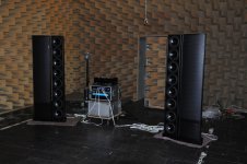
@Calvin thanks for your response! The esl setup looks impressive 🙂
"When fudging around with the XOver just make sure that the acoustic filter flanks are symmetrical."
Can you explain this? Sorry, my knowledge about filters is limited. I would assume one wants to maintain a polar response over the whole frequency. Do you mean by symmetrical the cross over curves?
I currently use a 48 dB/oct RL crossover for both LP and HP filter, at 200 Hz.
Hi,
(dynamic) speaker drivers are generally considered to have bandpass character.
The filter flanks very much depend also on the built-in condition.
While classic CB or BR casings alter the driver´s upper ends lowpass character not that very much, a dipole does.
The dipole´s response is characterized by rather sharp peaks and notches.
While the former may have a quite smooth amplitude response reaching considerably far above the xover point, the latter may show uneven response quite close to the xover point.
Similarly the response of a panel drops sharply below the pronounced fundamental resonance.
As the drivers responses are overlayed by the xover responses (adding up the dBs, resp. multiplicating when calculating with the transfer functions), the resulting response never equals the almost textbook ideal curves of the xover filters.
The closer the driver´s "flaws" in amplitude and phase response is located to the xover point, the more influence there is on the combined, the acoustical response.
An example: The first ML Sequel had a single bass driver working below the panel.
I measured a quite extended smooth amplitude response up to >1kHz iIrc.
The passive crossover (somewhere ~450-500Hz) was either 6dB or 12dB/oct, hence rather mild.
The combined response also showed that mild response.
The panel on the other hand showed the typical sharp fundamental resonance around 250Hz, with a associated hefty drop of ~36dB/oct underneath.
The Xover filter added ~12dB on top of that, making it almost 48dB/oct.
So the resulting acoustical filter flanks differed by about 6 filter orders (1order=6dB/oct)!
This gross asymmetry in the acoustic filter flanks was clearly audible.
As if it weren´t enough, the distribution character of panel and bass also changed at the xover point.
Sonically this resulted in the well known "fast film, slow cardboard" sound, that so effectively spoiled the image of the whole hybrid-ESL group.
Still not enough they used a crappy audio tranny to drive the panel and finally they put the bass into a BR cabinet.
Despite beeing such a technical design catastrophy the Sequal became quite popular ... which just proves how superior a decent hybrid ESL panel performs over dynamic speakers.
Now the bass dipole´s amplitude response at the upper end is much closer to the mirror image of the panel´s than a CB or BR bass.
Even soft XOver filters may result in quite steep acoustical flanks with a good chance of mediocre symmetry.
If You keep this in mind, You will quickly realize that standard XOver filters are rather poison than medicine for a hybrid-ESL concept.
It´s the acoustical filter flanks and their symmetry what counts.
jauu
Calvin
@Calvin: thanks again for your extensive response!
I realize that it is difficult to create a perfect filter based on in-room measurements. But even though I expect my current filter to be sub-optimal, after some hours of listening and comparing, I get the impression that the hybrid setup with line array woofers is integrating very well with my stats and produce a little more pressure in the lowest frequencies. It depends on the records, but with some specific records the difference is substantial. With others they sound very similar.
Currently I'm crossing over at 200 Hz, so now it looks inviting to build a new panel with smaller d/s distance. Currently I have loudspeaker cloth on the front and printing screen mesh on the rear to tame the fundamental resonance. These cloths help keeping dust away as well, and since I use them, I never had any problems with leaking bias voltage which resulted in some soft hissing sound close to the stats like my previous models had.
I remember that the addition of the printing screen and cloth had (minor) negative influence on the transparency of the sound. So removing them from this perspective would be tempting, but not sure how this will effect dust build up. Do you include screens / cloths to your panels?
Hi,
👍
so far I haven´t used screens or cloth, because transparent appearance was a major design factor.
So far I didn´t have problems with dust and fading bias.
I do install a circuit though that reduces bias to 1/2 in standby mode, or switch off alltogether.
I´m rolling a couple of ideas for new panel designs at the moment, where I would also like to test screens or similar damping means.
jauu
Calvin
- Home
- Loudspeakers
- Planars & Exotics
- My newest pair of DIY electrostatic panels, advice needed