there is another issue with the step down ... converters for negative in/out appear to be rare. I wonder how the industrial guys do it with their active speakers.
Isolated output converters are not uncommon, and they make the issue non-existent.there is another issue with the step down ... converters for negative in/out appear to be rare.
In general, they brew their own (or subcontract it, with an equivalent end-result).I wonder how the industrial guys do it with their active speakers.
There are reference designs available, mainly for class D, but they can be ported to class AB or Circlo which are much less demanding on the quality of the supplies
Ok I have been reading this post for hours. I am looking for boards to purchase does this exist anywhere? Also seen references to a build thread does that exist. Some version of BOM utilizing the MJL21194 as outputs.
Thank You
Thank You
I don't think someone made commercially available boards (but I could be wrong!!). Some people made a number of boards and they might still have some spare to sell.Ok I have been reading this post for hours. I am looking for boards to purchase does this exist anywhere? Also seen references to a build thread does that exist. Some version of BOM utilizing the MJL21194 as outputs.
Thank You
The build thread does exist: http://www.diyaudio.com/forums/soli...tion-parts-accessories-beginner-friendly.html
You can combine the MJL21194 with almost anything, there is no specific BOM for that.
The supply voltage (which ultimately means the max power output) is the main parameter having a small influence on the BOM, but that is well covered in Daniel's thread
I'll go for and with circlo because i tested it for "negative impedance", current drive, etc. Don't want to get into this with chip amps or class D. The ideal were 40 watts/ 20 watts.
The real issue are the active crossovers , matching the acoustical phase at crossover, frequency dependent limiter. The power amp should be just there and not get in the way. The circlo is right for that. Except that the idle dissipation ...
The real issue are the active crossovers , matching the acoustical phase at crossover, frequency dependent limiter. The power amp should be just there and not get in the way. The circlo is right for that. Except that the idle dissipation ...
Quick question; I know the answer is likely somewhere in this thread, but can anyone tell me whether anyone has designed a PCB and made it available for DIYers?
Boards and more
Take a look at Daniel's building threat:
http://www.diyaudio.com/forums/soli...tion-parts-accessories-beginner-friendly.html
If you wish: for cheap professional boards go to dirtypcbs.com
Take a look at Daniel's building threat:
http://www.diyaudio.com/forums/soli...tion-parts-accessories-beginner-friendly.html
If you wish: for cheap professional boards go to dirtypcbs.com
Last edited:
According to the tests I made, it is pretty tolerant, even without explicit Zobel:Hello Elvee,
Is this amplifier able to drive capacitive loads ?
http://www.diyaudio.com/forums/solid-state/189599-my-little-cheap-circlophone-5.html#post2590192
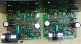
I completed my Circlophone today, both channels tested and all ok.
Some info:
I use 2x 0-24V to create +-30V DC PSU.
D8, D9 = 14V so I will get about 45W
R21 = 35K7
I use
- Onsemi BC560C for input, I tried 2SC970BL, 2SA1016, 2SA1015
- 2SC3423 for VAS with 4.7pF N0P ceramic capacitor
- Phillips BD140 for driver
- MJL21194 for output driver
- input cap = Claritycap ESA 4.7uf 250V
- dc block cap = Tantalum 150D 150u 15V
Sound ok for my taste.
Attachments

- MJL21194 for output driver
Congratulations! very impressive build. Do hear any low level hiss or noise with MJL21194's when you close your ears to speakers? I used these transistors but they weren't dead silent.
Congratulations! very impressive build. Do hear any low level hiss or noise with MJL21194's when you close your ears to speakers? I used these transistors but they weren't dead silent.
When I connected my source, I can't hear any low level hiss and noise with MJL21194 at normal condition when my ears was closed to the speaker. I'm not try to do that in the middle of the night when other sound is minimal.
I heard some very very small noise before with my prototype but not with the final PCB.
Very nice build. If you have spare boards, you can offer them for sale: I think some members would be interested, for example:I completed my Circlophone today, both channels tested and all ok.
Some info:
I use 2x 0-24V to create +-30V DC PSU.
D8, D9 = 14V so I will get about 45W
R21 = 35K7
I use
- Onsemi BC560C for input, I tried 2SC970BL, 2SA1016, 2SA1015
- 2SC3423 for VAS with 4.7pF N0P ceramic capacitor
- Phillips BD140 for driver
- MJL21194 for output driver
- input cap = Claritycap ESA 4.7uf 250V
- dc block cap = Tantalum 150D 150u 15V
Sound ok for my taste.
Ok I have been reading about this amp for a couple of days now. I am looking for boards most likely for the original circuit are there any available? I do not plan on making my own. Has anyone had some made and how would I do the same? Any info would be helpful. BTW, MJ21194's(2) can support up to how much power into 4 ohms?
Quick question; I know the answer is likely somewhere in this thread, but can anyone tell me whether anyone has designed a PCB and made it available for DIYers?
Very nice build. If you have spare boards, you can offer them for sale: I think some members would be interested, for example:
I have 4 boards left from the order. But the shipping fee from my country seem very high so it is not worth it. But I can share the Geber files if any one need them.
Last edited:
When I shorted input and try to measure AC on output, I got about 26->27mV on both boards. Is it normal or too high?
AC? That's completely abnormal. First thing to do is to look at the waveform with a scope, since you hear nothing, it must be ultrasonic or subsonic.When I shorted input and try to measure AC on output, I got about 26->27mV on both boards. Is it normal or too high?
Try also to confirm your measurement: measure, and then remove the power, does the voltage disappear? Do you have some appliance in the vicinity, charger, etc: SMPS's tend to radiate.
It could also be 50Hz hum: if it is pure, with low efficiency speakers it could be inaudible.
It could be an internal oscillation, but the level should be higher then, unless your meter is unable to work properly at that frequency
It is strange, when I connected an inpod as source, it became 15mV and when twist V+ V- GND it became 12mV.
My DMM is a normal one so AC measure are useless. I will try to work on to indentify this depend on yout listing cases. It will be much easier if I have a scope but I didn't.
My DMM is a normal one so AC measure are useless. I will try to work on to indentify this depend on yout listing cases. It will be much easier if I have a scope but I didn't.
From what you describe, it looks like it comes from an external interference. In a modern living environment, this makes all electronic devices suspect, even the most banal of the light bulbs (actually a CFL)
Thanks! You are right! I tried to check grounding, twist wires and check again at day time (when neighbours go out for working), I can get ~ 0.000V on AC measure (input shorted) so I think my amp was ok.
Last edited:
I have just completed the Piersma inverted Jfet version. Everything looks and sounds ok so far. the only thing I see is I have 30mvdc at the output. Is this too high? I did not try to match any semi's. Isn't this usually a mismatch at differential front end of SK170's? Is there a way to add resistance to one of the bases to get closer match?
- Home
- Amplifiers
- Solid State
- ♫♪ My little cheap Circlophone© ♫♪