
You are right. I too did not find any difference with or without gate stopper resistors in simulation. Elector circuits normally use 220 Ohms gate stopper resistors. here in India I have found that most of the MOSFET based amplifier use 47 to 100 Ohm resistors.I checked HexFet sim and it looks the same with or without gate stoppers.....
Indeed: I made a quick and dirty job of inserting the BS diode directly into the +railI think you can gain another 0.5V by connecting op-amp positive rail 'before' the bootstrap...
That looks nice and like 'organically grown'. Maybe even vegan? 😀
Congratulations on good work. It shows the quest of old Circlophone lovers to improve it further.
Very good to see organic improvement to the already excellent performing amplifier. Such improvements may one day place this amplifier in expensive HIFI range category.👍
Very good to see organic improvement to the already excellent performing amplifier. Such improvements may one day place this amplifier in expensive HIFI range category.👍
Hello Minek,
I’m absolutely thrilled to see you reapply your (not insignificant(!)) skills to this fine piece of engineering.
A few technical questions, if you don’t mind:
What am I missing here?
Thank you in advance.
Tonny
I’m absolutely thrilled to see you reapply your (not insignificant(!)) skills to this fine piece of engineering.
A few technical questions, if you don’t mind:
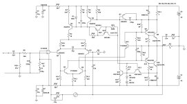
- How critical do you expect your design to be to the exact choice of rail voltage and output stage transistors?
- What is the function of the huge bipolar capacitor C11 in the negative feedback circuit of the op-amp?
- The voltage supply for the op-amp appears to me as rather “minimalistic.” Is the PSRR of the op-amp and/or the Circlophone really so good that more attention to supply noise isn’t worth the effort?
What am I missing here?
Thank you in advance.
Tonny
How critical do you expect your design to be to the exact choice of rail voltage and output stage transistors?
Rail voltage can be changed with no problems. Some of the resistors (E.g. Zener resistors) will need to be re-calculated.
Changing output transistors (E.g. for faster ones) will require re-running the sim, and most likely adjusting
feedback/compensation values (R30,C12,C2,C5,C4).
Same for drivers.
What is the function of the huge bipolar capacitor C11 in the negative feedback circuit of the op-amp?
It will cause the gain of the amp to be a unity at DC, and it will greatly reduce creation of output DC offset value.
This is typical solution for blocking DC - to make sure there is 0V DC at the output of the amp.
Without it you may see more DC voltage at the output than you want.
If your input circuitry takes care of it in some other way (E.g. input LTP pair on one die and well matched), this capacitor might be omitted (shorted).
I usually provide space for it on the PCB, and test amp with cap shorted. If my output DC is below 5mV and stable with temperature, the cap is not needed.
For more details see Cordell's book, chapter 3.11 ("Feedback AC decoupling network").
The voltage supply for the op-amp appears to me as rather “minimalistic.”
Op-amp only draws 5mA, in my opinion Zeners + caps will be good enough.
I guess using more complex regulation will not hurt, but after building several amps with Zeners like this, I don't see/hear any problems...
Nice project 🙂
For schottky diodes which one would be best suited for this circuit between these two?

For schottky diodes which one would be best suited for this circuit between these two?
Let's see what Elvee says.
But in my 2 builds of the original Circlophone, I used SR504 diodes
https://www.mouser.com/ProductDetail/Taiwan-Semiconductor/SR504?qs=JV7lzlMm3yLakOwkJg0XMg==
From my notes from 5 years ago, I can see that SBR10U and SB140 were also being considered, and I also have them is stock:
https://www.digikey.com/en/products/detail/diodes-incorporated/SBR10U45SD1-T/4250086
https://www.digikey.com/en/products/detail/onsemi/sb140/1049003.
MBR735 was used in the sim, because it's model is built in LTSpice.
These diodes do not run hot, and don't need to be so big.
For D7, these diodes can be used: BAT81, BAT85, BAT86, BAT54
All resistors can be 250mW, except:
R11, R16 0.5W - 1W
R30 - 0.5W
R26, R29 - 0.5W - 1W
R24 - 1W - 2W
C11 should be non-polar, 6V3
C9 - if using electrolytic cap - also non polar
Zeners - any Zener 0.5W - 1W
Last edited:
570mVNice project 🙂
For schottky diodes which one would be best suited for this circuit between these two?
View attachment 1348948
The lower forward drop the better: the role of the diodes is to reduce the losses by increasing the output swing, but the effect is rather minuscule, and I have tested ordinary Si diodes in that role. The only effect was a small reduction of the output powerNice project 🙂
For schottky diodes which one would be best suited for this circuit between these two?
View attachment 1348948
The spread of vias and the component placement a bit unusual. There is one thing I can notice: the vias going to output terminal could be thicker and the Output terminal hole and the footprint could be bigger, like the ground post between rail caps.That looks nice and like 'organically grown'. Maybe even vegan? 😀
That's right, I'd reinforce that with a cu wire soldered onto the trace if the board is already on order and can't be changed anymore.
My PCB will have all the wires soldered to the PCB from the bottom. No posts or connectors on the pcb, no visible wires...
Kind like in this example of my original circlophone build:
https://www.diyaudio.com/community/threads/my-little-cheap-circlophone-c.189599/post-5952530
I understand that's not the way most of people would build it..
Or another one (with active cooling) in this photo:

Kind like in this example of my original circlophone build:
https://www.diyaudio.com/community/threads/my-little-cheap-circlophone-c.189599/post-5952530
I understand that's not the way most of people would build it..
Or another one (with active cooling) in this photo:
Last edited:
I would indeed build it differently. I'd at least try to get the power trans a lot closer to the board (or vice versa),
TO-3 output transistors will work just fine with 5cm wires connecting them to the PCB.
Alternatively, plastic outputs can be soldered directly to the board - that's how the circlophone in the photo above was done..
Alternatively, plastic outputs can be soldered directly to the board - that's how the circlophone in the photo above was done..
Is the silkscreen for the NP 470uF capacitor supposed to show a polarized capacitor symbol with a + on one lead rather than a symbol for a NP capacitor? Maybe it's intentional, just pointing it out.
- Home
- Amplifiers
- Solid State
- ♫♪ My little cheap Circlophone© ♫♪