Progress so far.
Will finish in October.

Will finish in October.

I'm older now and when I was young I always said I can hear differences. Now I'm not sure of that. I do not have memory of the fact that I can hear differences between amps with near equal specs and components. It is all subjective and just as minek123 said, "The problem is that one day I like amp A better, the other day amp B", so do I it depends on the condition of my ears and how well I slept, did I have a quarrel with my wife, tc.😉Now what is the definition of "the same"??
Here is my experience: If I switch from amp A to amp B, it doesn't sound the same.
I feel differences. Then I switch to amp C. Also feel differences. Then switch to A again - feel difference.
I can't tell which sound is ''better' or 'worse'. Just different.
I can tell which one I like better. The problem is that one day I like amp A better, the other day amp B.
All in all, if I repeat these tests many times in different order, different amps, blind or not,
there is clearly NO PATTERN of which amp I prefer.
This is mine. Still working on it for more than a year, adding every week some stuff. It is build with new transistors but all other components are coming from used amplifiers. I love it to recycle old components, even old capacitors, checking, measuring and use it.

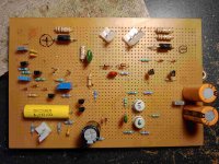
I liked the layout of the PCB as all heat generating devices are on the main heat sink.
The pot (10K) is in series with R21 (33K) to adjust the current to around 1.4mA. I had to deal with varying voltages from the power supply (22V to 27V DC) in the amplifiers.What for this Variable resistor pot has been used?
View attachment 1357916
Circlophone does not use any pot.
OK.The pot (10K) is in series with R21 (33K) to adjust the current to around 1.4mA. I had to deal with varying voltages from the power supply (22V to 27V DC) in the amplifiers.
You could also try two transistor CCS in place of R21 which works quite well and stable with different rail voltages.
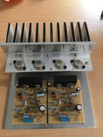
This week I worked on the mechanical part, the cooling for the 2N3055 transistors. I used an aluminum heatsink from an old receiver and used two 2 mm L-profiles back to back to form a 4 mm T-profile and screwed it to the heatsink. I found also a 5 mm thick aluminum plate and use it as a ground plate for the heatsink and amplifier board. I know the black insulators are at the wrong side, they are just for testing if the holes are the right size. 😉
Attachments
Sorry for delay with finishing the op-amp based circlophone, but I'm trying to take advantege of the last days of the season with good weather,
and finish my other renovation project (25 years old off-road truck):

and finish my other renovation project (25 years old off-road truck):
I recently built a digital amplifier based on a high quality TPA3255 board for my curiosity, especially its performance against my Hexfet Circlophone. Even though TPA3255 is very popular amongst digital amplifier builders but it has no chance against my Hexfet Circlophone in terms of sound quality. Circlophone has more clarity, better dynamics and better attack. Vocals are very natural and very organic on Circlophone.

Thanks terranigma. Interesting work.
Did you have some problems with the tuning and the results?
Did you have some problems with the tuning and the results?
I've built many Circlophones and I've never experienced tuning and stability issues with them. If it powers up first with no issues, you can just enclosure it. VAS transistors (Q5 and Q6 in original schematic) are crucial to get desired sound. If your VAS transistors are not fast enough, you are going to have rolled-off trebles. Those are the ones you have to pick carefully.
Finally managed to test op-amp based Circlophone.
As expected, everything worked right off the bat. Connected PSU, oscilloscope, wave generator, and voila!
Tested 1 channel only, with plastic output devices (final build will be done with TO-3 devices), 42V rails, and little bit over 240mA
of idle current.
Small temporary heatsink for output devices (isolated with kapton tape and held with this serious looking carpenter clamp)
is slightly warm but not hot.
From the square waves test it seems like Slew Rate might be matching the simulation (90 V/us).
I measured rise time 900ns at 18Vpp which translates to 52V/us
Schematic exactly like in the post #2486.
Photos attached. No music test yet.
Next step - test 2nd channel, and assemble everything on the Alu chassis with proper heatsinks.
- Home
- Amplifiers
- Solid State
- ♫♪ My little cheap Circlophone© ♫♪