Hello,
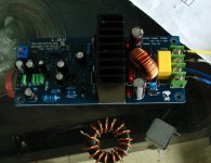
I bought a pair of the L25D (mono) a few months ago. The output inductors are running very hot, up to 80 deg Celsius. I afraid the whole amp will blow one day, so I open up the inductors, rewind with Litz wire, and now the inductors stay below 50 deg Celsius. Any comment on this ?
Thanks.
Obviously you did the right thing. With significant ripple currents of several 100Khz, proximity effect between windings is the problem. So your experience is no surprise to me.
But litz wire is more expensive than simple enamelled copper wire.🙄
Hello,
I bought a pair of the L25D (mono) a few months ago. The output inductors are running very hot, up to 80 deg Celsius. I afraid the whole amp will blow one day, so I open up the inductors, rewind with Litz wire, and now the inductors stay below 50 deg Celsius. Any comment on this ?
Thanks.
I think the cause of heat is not LITZ WIRE.
But the inductance value, maybe you to modified inductance is less than 22 uh.
The attenuation of the 400 k PWM signal voltage will be reduced.
22 uh can put about 70 V voltage attenuation is 0.3 V.
If smaller inductance, 10 uh, voltage will get 1 v. Heat will decrease, but it is not a good thing.The resistance of the LITZ wire will not get smaller.
I rewind the inductors to exactly 22uH. Wiki has nice explanation, litz wire reduce the skin effect and proximity effect losses in conductors used at frequencies up to about 1 MHz .
BTW, I got the litz wire from old crt monitors, usually they have a few inductors with litz wire inside them.
BTW, I got the litz wire from old crt monitors, usually they have a few inductors with litz wire inside them.
I use t106-2 cores with 22SWG enamelled copper wire on my amplifiers and they barely get warm.
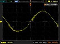
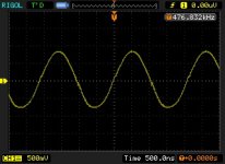
B: yes. Red loop inductance temperature is low.
But the bigger output signal distortion.
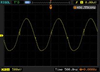
No signal input, direct measurement output PWM waveform changes obviously.
After the input signal, maybe the ear is not necessarily can recognize a lot of changes.
But I still like the waveform design is more beautiful.😉
This is my test:
Attachments
Last edited:
I rewind the inductors to exactly 22uH. Wiki has nice explanation, litz wire reduce the skin effect and proximity effect losses in conductors used at frequencies up to about 1 MHz .
BTW, I got the litz wire from old crt monitors, usually they have a few inductors with litz wire inside them.
Very thank you for your opinion. I'll get in touch with inductance manufacturer engineer immediately.
Production samples. Hope I will soon the results.
😀
Hi,
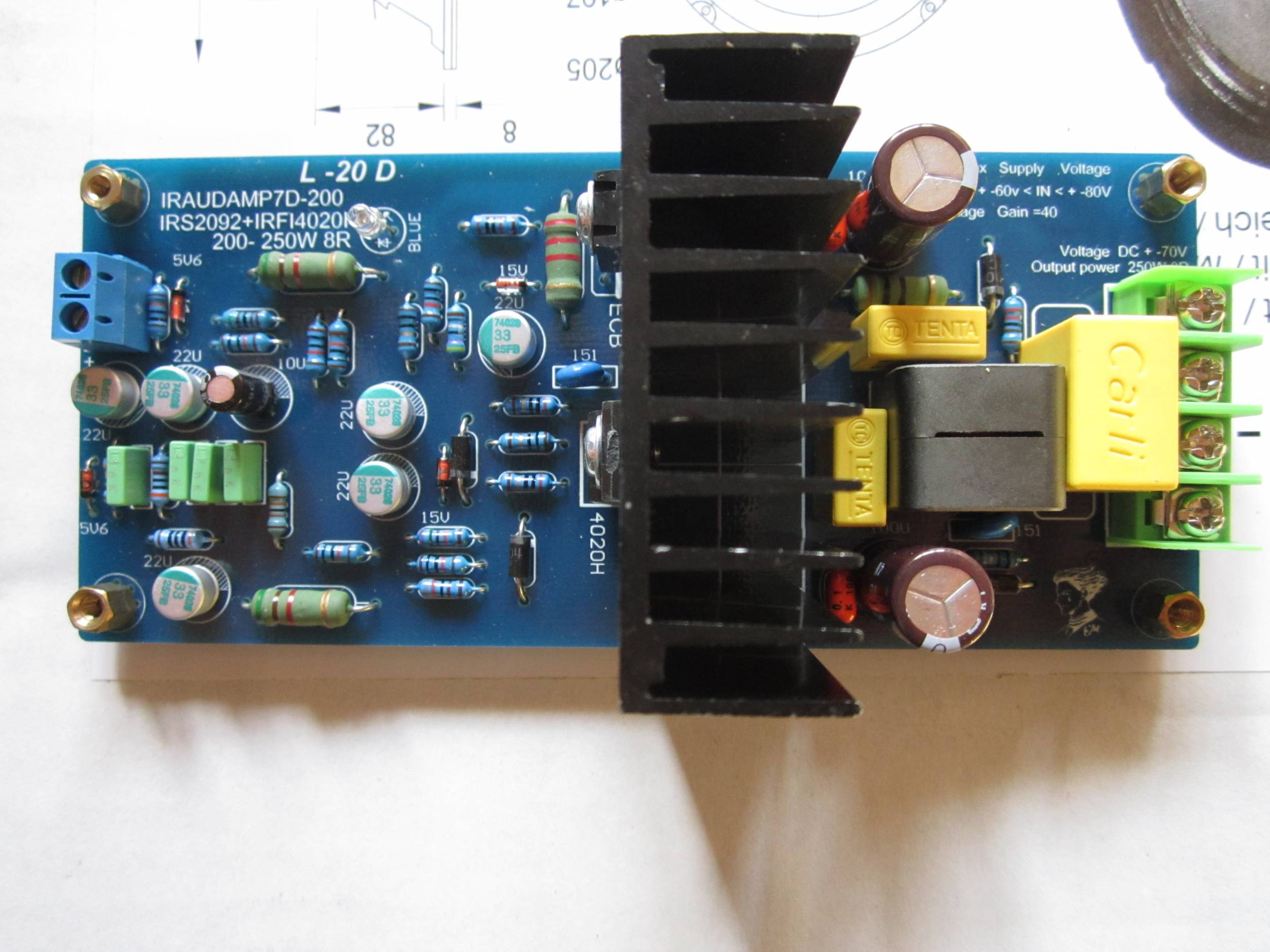
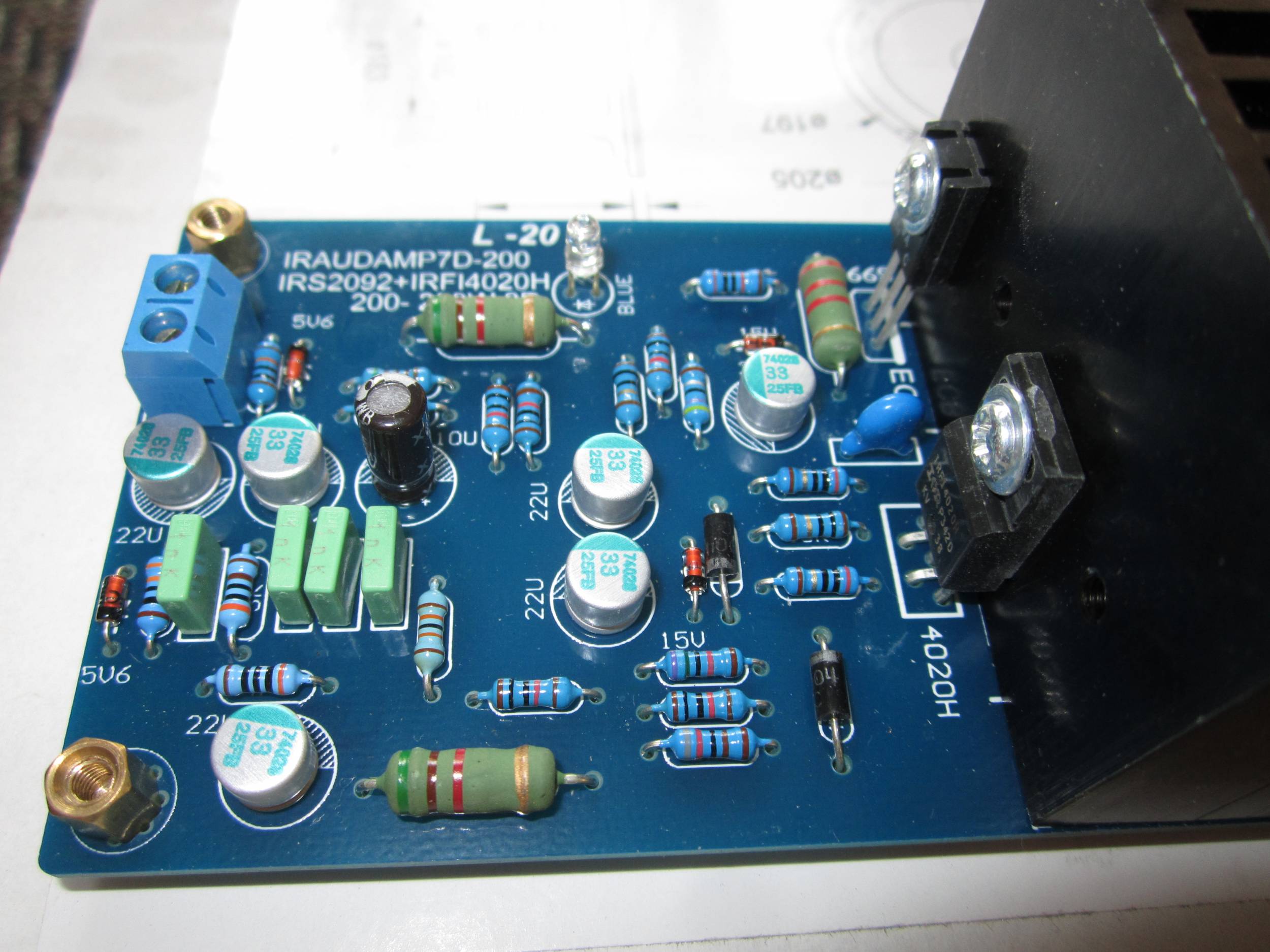
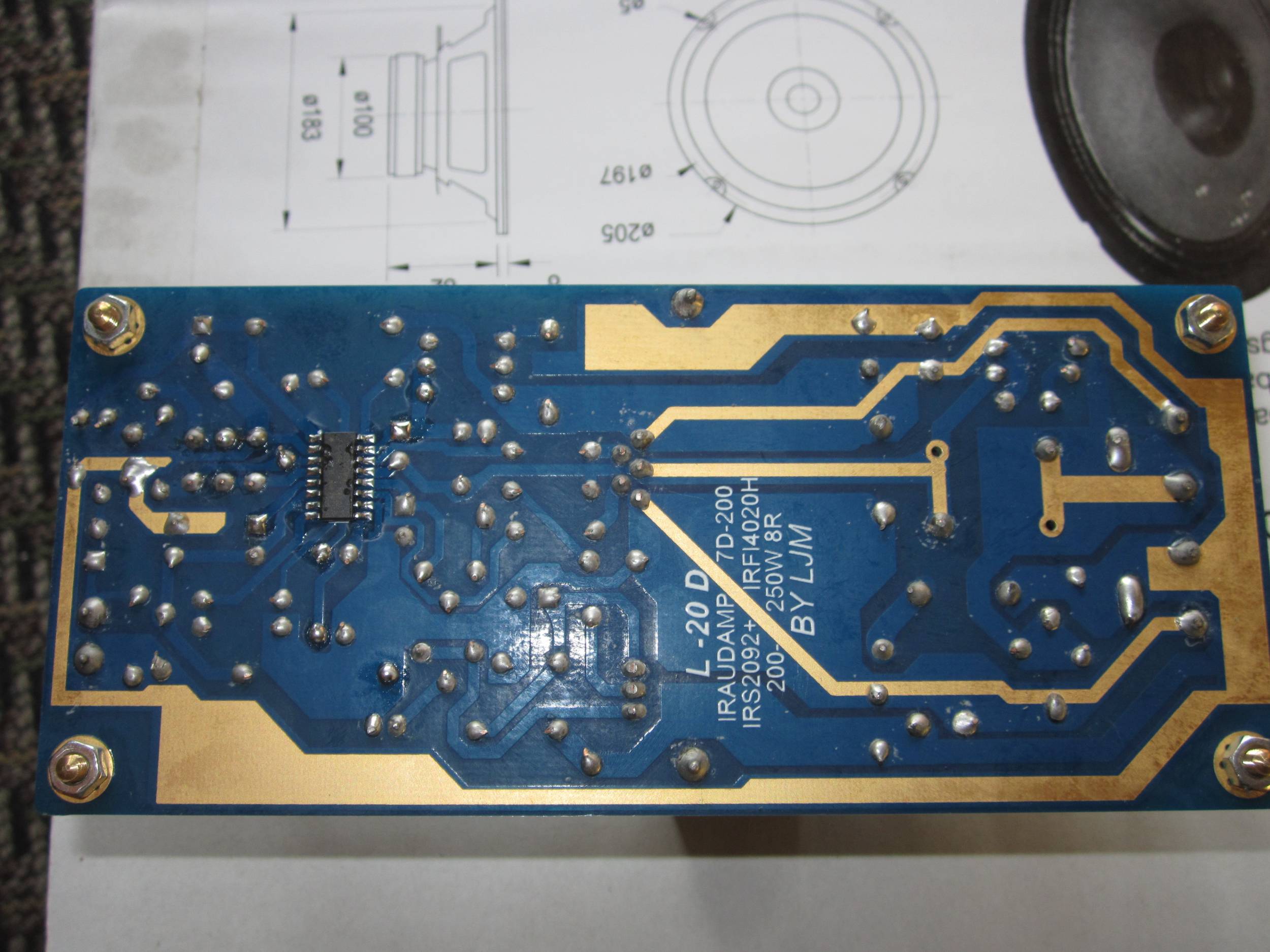
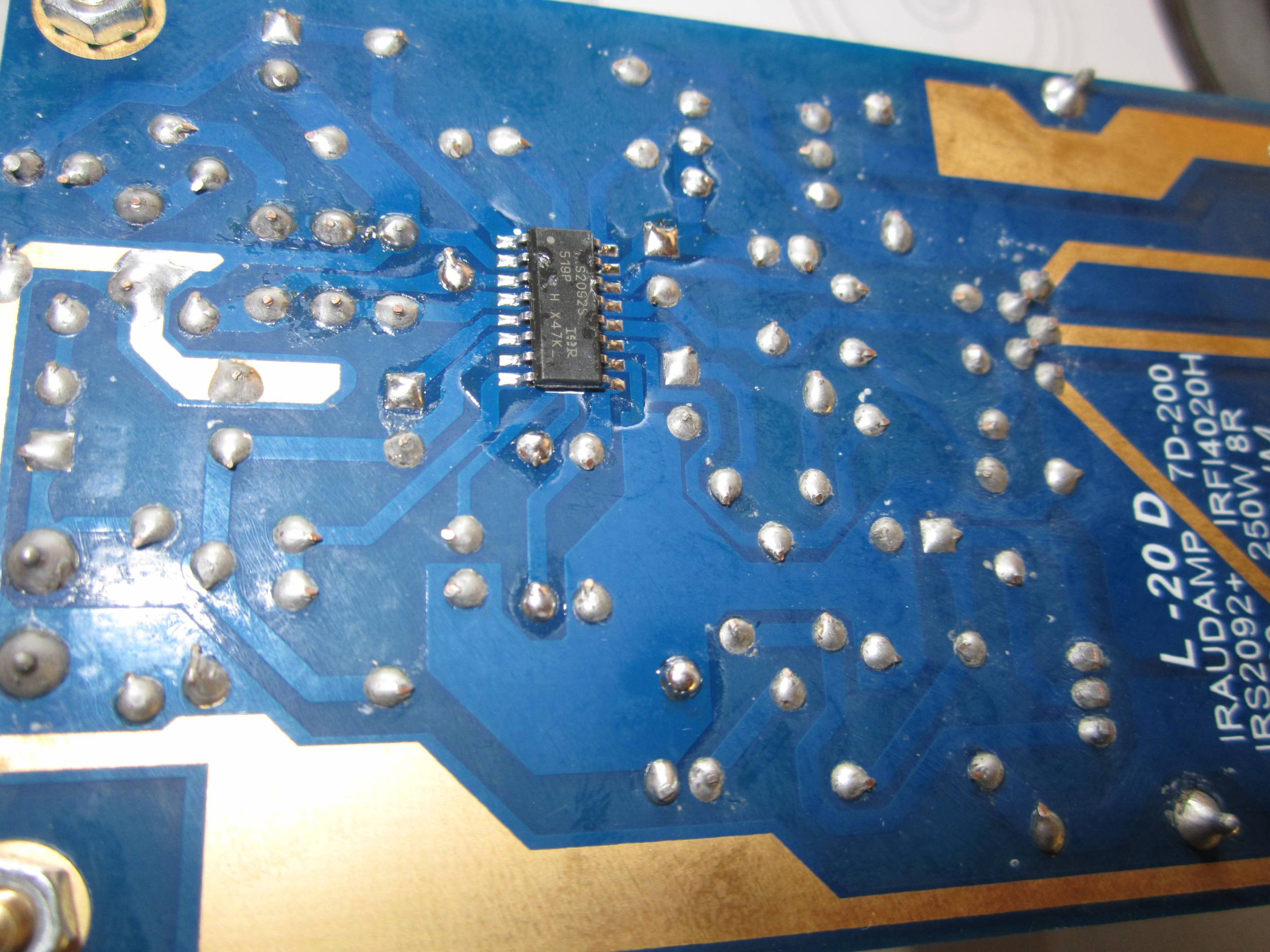
I just bought already soldered L20D amp from jlm_ljm recommended seller ZOE_TSANG throgh aliexpress and have serious doubts about quality of parts used. In general all electrolytic caps are small alu type and all caps are wrong values (33 UF instead of 22 UF and 150UF instead of 100UF in power rails. I think power rails should be ok, but what about these 33UF caps. Should I have to change them? Please take a look on another parts used. Are they ok?
I rewind the inductors to exactly 22uH. Wiki has nice explanation, litz wire reduce the skin effect and proximity effect losses in conductors used at frequencies up to about 1 MHz .
BTW, I got the litz wire from old crt monitors, usually they have a few inductors with litz wire inside them.
Now I use g23a instead of the original version 7G17A.
To reduce the temperature of the 20 degrees Celsius.
I think it is very ideal.
Including L20D L25D, L30D use 7 g23a inductance
😎
Hi,
I just bought already soldered L20D amp from jlm_ljm recommended seller ZOE_TSANG throgh aliexpress and have serious doubts about quality of parts used. In general all electrolytic caps are small alu type and all caps are wrong values (33 UF instead of 22 UF and 150UF instead of 100UF in power rails. I think power rails should be ok, but what about these 33UF caps. Should I have to change them? Please take a look on another parts used. Are they ok?
You buy the product no problem.
33 uf is improved. Better than 22 uf.
33 uf use OSCON solid capacitors. The work is more suitable for high frequency PWM.
150 uf 100 uf position. It is very good.
Japan chemical NCC LXY series.
Attachments
Last edited:
hello, i'm a bit off topic, i have a question about L15D, my voltage will be 52v without load, and my first question is about power suply capacitors, is the rated voltage of 63v enough or do they have to be higher? second question is about on board rail capacitors.. do they have to be 100uF-150uF or the bigger the beter? and the rated voltage of those capacitors, 63v enough or they must be higher? is a low ERS of this capacitors good or it dousn't matter ? Thanks. Jaka
Cabinet used for amplifire
Hello Rens,
Your cabinet matches your Emotiva av amplifire nicely.
Where is this cabinet for sale.
Best regards Jan
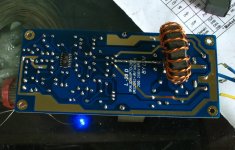
I cut a toslink cable in five pieces and connected them to the blue led's with a piece of 3mm ID tubing . The other side of the 1 mm fiber sticks in to the front panel and that makes a 1 mm blue Led , and that looks pretty cool !
Cheers ,
Rens
Hello Rens,
Your cabinet matches your Emotiva av amplifire nicely.
Where is this cabinet for sale.
Best regards Jan
Hello Rens,
Your cabinet matches your Emotiva av amplifire nicely.
Where is this cabinet for sale.
Best regards Jan
Sorry Jan , Fully DIY , read this : http://www.diyaudio.com/forums/clas...-irs2092-irfi4020h-200w8r-41.html#post2997024
I made some modifications to the Amp , It's now powered by Connex SMPS2000RxE with build in DC protect , triggered by DC sense boards from : http://www.diyaudio.com/forums/vend...-mosfet-amplifier-module-102.html#post3955803
Works perfect , So I could remove the protection relay boards . I raised the supply voltage to +/- 55 Volts , so have the full 5 x 150 watts at 8 ohm available . Very impressive ! And the powersupply has no problems at all delivering this power !
Cheers ,
Rens
Hello Rens,
Thank you for the quick reply. It is clearly outlined how you build your cabinet.
Your mod on the supply is well taken.
I'am in the process of ordering. I will delete the protection boards.
I'll use a Hypex SMPS.
Cheers,
Jan
Thank you for the quick reply. It is clearly outlined how you build your cabinet.
Your mod on the supply is well taken.
I'am in the process of ordering. I will delete the protection boards.
I'll use a Hypex SMPS.
Cheers,
Jan
Hello,
I need your advice, if there is any. I made my amplifier with two L25D and an SMPS power supply. It works well, sounds well with a CD player, but it is not usable with a tuner, because the tuner gives no right signal, only big noise wich i think comes from the amplifier by the power cable and the antenne.
Any advice? Thanks
Hello,
I need your advice, if there is any. I made my amplifier with two L25D and an SMPS power supply. It works well, sounds well with a CD player, but it is not usable with a tuner, because the tuner gives no right signal, only big noise wich i think comes from the amplifier by the power cable and the antenne.
Any advice? Thanks
I'm sorry I didn't catch your meaning.
If detailed case, should be able to handle.
Are you saying that there is no right signal input?
he's saying that the class D amplifier emits so much rf noise that it fouls up the radio tuner, which I have also personally observed. I have also found partial solutions to this.
If you want to have a properly functioning tuner in presence of a class D amplifier, you are going to have to knock down the rf noise as much as possible.
1: contain the amplifiers in a grounded, metal enclosure
2: put ferrite beads .. probably double ones (two in a row) on all three power connections as well as audio output lines. Particularly the audio output lines
3: if that is not adequate, then the next step is to place small 5 uh or so inductors in the audio output lines inside the grounded metal enclosure. This will convert the 2-pole output filter to a 3-pole filter and get you 18db/octave drop in noise past something like 100 khz.
4 if that still isn't enough, you may try putting 0.1 uf nonpolar caps between audio output and 0 volts after those inductors. Probably put those caps in series with 1 ohm 5 watt to help kill any resonances.
It's important to understand that the output filter can potentially store energy that somehow gets back into the feedback loop and creates parasites. So, damping resistors can help solve that problem (like the 1 ohm 5 watt) any damping resistor directly in the audio output path would have to be 0.05 ohm or smaller I would think. ljm_ljm was wise and put this kind of dampening on board the L25D, so there is some of it already there, but if you start building out the output filters to kill rf, you may need more of it.
If adding filter components causes a parasite to arise, the heat sink will heat up aggressively, so after adding anything other than a ferrite bead at the output, which acts as a dampener its self, keep your finger on that heat sink to see if it gets hot. If it gets hot, you have created a parasite, and you have to add dampening into the circuit to kill it.
It is also worth putting a ferrite clamped around the mains cable, as close to the amplifier as possible.
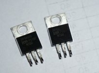
Please note that in the 2016-2-10, there are about 10 sets during the 2016-3-17 day L25D power tube appeared quality problem.
They weave number is IRFB4020 P515P WIQU and P445 TF46 both.
If you meet this number. Please contact me.
I will contact the agent business arrange mailing IRFB4020 transistor.
The transistor will be increased the radiator temperature anomaly, severe cases may be damaged.
They weave number is IRFB4020 P515P WIQU and P445 TF46 both.
If you meet this number. Please contact me.
I will contact the agent business arrange mailing IRFB4020 transistor.
The transistor will be increased the radiator temperature anomaly, severe cases may be damaged.
Attachments
What's the best way to wire up two of these boards for use as a subwoofer amplifier? The speaker is a single subwoofer with dual 2-ohm coils.
1) One amplifier connected to each VC. Reduce supply voltage to +/- 45V to reduce max current levels into 2-ohm load.
2) Connect load in series (4 ohms net) and bridge the two output channels. Can the outputs be used in parallel or should they be in series?
Another question:
To reduce bass pumping shall I reverse the input and output signals on one board? Power supplies are two Meanwell NES-350-48V (to be wired for +/- 48V). Should I consider adding some capacitance to the 48V supplies, and if so, approximately how much?
- Home
- Amplifiers
- Class D
- My design L20D IRS2092+IRFI4020H 200W8R