Now making heat sinks, soldering and testing PCB's carefully.
Shouldn't be to long before some FFT fun and listening tests!
Stay tuned.
Shouldn't be to long before some FFT fun and listening tests!
Stay tuned.
So after ordering some aluminum angle that’s 3.2mm thick, 45mm by 25mm.. Only after cutting to size I realized that it was far to large to use for my DIY heat sinks. Dough!
Now I have decided to use 15mm, 40mm and 1.5mm thick. Much more like it!
For the heat sink ‘fins’ I used 20mm, 20mm U profile.
After a lot of sawing, drilling, filing and finishing. I have these parts:

Here is how they look mounted on the power supply board:

Power supply testing went well, with extremely low ripple under load in the millivolts, both for high voltage and filament voltage.
I tuned the filament voltage to ramp up quick enough to prevent cathode stripping, but slow enough to reduce the inrush current to a sensible level from a cold filament.

Thinking of the next step the preamp itself. It uses a JFET input, bootstrapped tube VAS and MOSFET output. The amp is also non-inverting.
I fired up the soldering iron to get started on the preamp PCB:

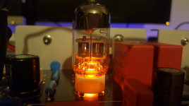
Construction went well, and the tube socket (complete with slightly gimmicky orange LED underneath) seems to cope OK with the physical stress of inserting and removing tubes, although this was a slight concern.
I picked 2 of the closest matching resistors for R16 to help match L and R channels gain as they are only 10% tolerance resistors. As well as making a mount to keep the resistor cool:

Now I have two completed preamp boards:


Now for the testing..
B+ high voltage sat at about 260V
Distortion seems to reduce slightly at a higher bias (as predicted), so I settled on 155V that held very stable (+/- 1V) for about an hour of testing:

Now for a look at distortion, the load test is a 10k resistor.
Here is an FFT at 30V peak-to-peak:

Frequency response is a non-issue, it’s as flat as my sound cards outputs:

_________________________________________________________________
Overall I am very happy with these results, especially being my first valve project.
It hits all the goals I set out to hit, I have had an hours listening test and sounds pretty good to my ears, the noise floor seems extremely low, no buzz or hum (despite missing C1 that I will order later). I look forward to listening in stereo to assess the amp properly.
The heat sinks run cool, in the mid 30C range so should be fine in a vented case.
So the most important work is done, but its by no means over. I still have to construct a chassis and front panel control PCB for pots, switches input select relays and so on.
The chassis is planed to measure 400mm by 400mm and around 85mm tall. A big amp.
I'm thinking of using 2/3mm aluminum for the bottom floor and front and back, perforated sheet with 8mm hole size for the top, and nice wooden sides.
Here is a rough layout of how it may look:

I will also attach full final schematics for my build and hope it will be useful as its quite a unique design.
Now I have decided to use 15mm, 40mm and 1.5mm thick. Much more like it!
For the heat sink ‘fins’ I used 20mm, 20mm U profile.
After a lot of sawing, drilling, filing and finishing. I have these parts:
Here is how they look mounted on the power supply board:
Power supply testing went well, with extremely low ripple under load in the millivolts, both for high voltage and filament voltage.
I tuned the filament voltage to ramp up quick enough to prevent cathode stripping, but slow enough to reduce the inrush current to a sensible level from a cold filament.
Thinking of the next step the preamp itself. It uses a JFET input, bootstrapped tube VAS and MOSFET output. The amp is also non-inverting.
I fired up the soldering iron to get started on the preamp PCB:
Construction went well, and the tube socket (complete with slightly gimmicky orange LED underneath) seems to cope OK with the physical stress of inserting and removing tubes, although this was a slight concern.
I picked 2 of the closest matching resistors for R16 to help match L and R channels gain as they are only 10% tolerance resistors. As well as making a mount to keep the resistor cool:
Now I have two completed preamp boards:
Now for the testing..
B+ high voltage sat at about 260V
Distortion seems to reduce slightly at a higher bias (as predicted), so I settled on 155V that held very stable (+/- 1V) for about an hour of testing:
Now for a look at distortion, the load test is a 10k resistor.
Here is an FFT at 30V peak-to-peak:
Frequency response is a non-issue, it’s as flat as my sound cards outputs:
_________________________________________________________________
Overall I am very happy with these results, especially being my first valve project.
It hits all the goals I set out to hit, I have had an hours listening test and sounds pretty good to my ears, the noise floor seems extremely low, no buzz or hum (despite missing C1 that I will order later). I look forward to listening in stereo to assess the amp properly.
The heat sinks run cool, in the mid 30C range so should be fine in a vented case.
So the most important work is done, but its by no means over. I still have to construct a chassis and front panel control PCB for pots, switches input select relays and so on.
The chassis is planed to measure 400mm by 400mm and around 85mm tall. A big amp.
I'm thinking of using 2/3mm aluminum for the bottom floor and front and back, perforated sheet with 8mm hole size for the top, and nice wooden sides.
Here is a rough layout of how it may look:
I will also attach full final schematics for my build and hope it will be useful as its quite a unique design.
Attachments


As for transformers I thinking of using the Triad Magnetics VPT series.
Triad Magnetics VPT18-2780: 9V / 18V - 50VA [https://www.mouser.co.uk/ProductDetail/Triad-Magnetics/VPT18-2780?qs=wkKrz7WmEgOsofzfskZP0w==]
Triad Magnetics VPT230-220: 115V / 230V - 50VA [https://www.mouser.co.uk/ProductDetail/Triad-Magnetics/VPT230-220?qs=wkKrz7WmEgMVJQHjyRuIng==]
I know the high voltage transformer will result in around 325V DC after rectification, that's 65V to high that will need to be dropped by the power supply's MOSFET.
I cant seem to find a more suitable lower voltage transformer on Mouser. Not ideal but as long as the 400V rated capacitors hold up, it should be OK.