Electrical code will not accept that thinking for reasons of safety. Earth ground is your best chance of not getting zapped good and hard if there is a problem. Fuses are great but too late for such events. Given the fact that your house voltage is at ~220 AC~ that should be even more of an incentive to be safe. The chassis grounded to earth is what you need to do and won't have an effect on the sound anyway (unless there are already problems with it to begin with).

Only reason I say leave disconnected from house earth is because the transformer I'm using is an external plastic 12Vac one, terminating in a single barrel jack. It didn't seem right to me to not have a path to house earth, but I have seen equipment with a 'ground lift' switch.
I'm going to switch to toroidal transformers instead rather than EL, do it properly.
I've seen one 230Vac > 230Vac at 25VA for high voltage B+
and another for filament 230Vac > 9Vac at 50VA, I will just switch to 5V relays.
Then wiring both primary's together is what I'm thinking...
I've seen one 230Vac > 230Vac at 25VA for high voltage B+
and another for filament 230Vac > 9Vac at 50VA, I will just switch to 5V relays.
Then wiring both primary's together is what I'm thinking...
The wiring is fine as you describe connecting it. I am no expert so I will just ask the question. Do you need a 50VA transformer for the heater supply? The bigger transformer, the bigger the magnetic field. I tend to think the same way, and then I have to deal with the results.
Next one down is 25VA at 9Vac, It's only £5 less.
They are made by Triad Magnetics, Models:
VPT18-1390
VPT230-110
I plan to use a fused IEC connector straight to the transformers like so:

They are made by Triad Magnetics, Models:
VPT18-1390
VPT230-110
I plan to use a fused IEC connector straight to the transformers like so:
Triad makes a good product. My question concerned magnetic field, not price. maybe your internal arrangement within the chassis will allow for the larger magnetic field.
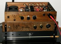
My present build is also a preamp with two 12AU7 tubes in circuit. I am using a 25 VA for the heater supply, and a separate 25 VA for the B+ supply. It is the top unit shown in the picture. Still have a ways to go, but it is functional for now.
My present build is also a preamp with two 12AU7 tubes in circuit. I am using a 25 VA for the heater supply, and a separate 25 VA for the B+ supply. It is the top unit shown in the picture. Still have a ways to go, but it is functional for now.
Attachments
Last edited:
Very nice! I was thinking of using a lot of wood in construction too, made from scratch, so however big it needs to be is how it will be made (within reason)
Where did you get the toroid covers? and is the input selector straight switches or relay based?
Where did you get the toroid covers? and is the input selector straight switches or relay based?
I shall start the preamp test PCB's. Maybe I should also try an SRPP in place of the bootstrap:

Distortion reports at 0.14% at 13.6Vac. Not bad, but the biasing via R8 and R5 seems to effect distortion much greater than the resistor (and bootstrap) approach.
Distortion reports at 0.14% at 13.6Vac. Not bad, but the biasing via R8 and R5 seems to effect distortion much greater than the resistor (and bootstrap) approach.
PCB almost done, using the following circuit:

D1,3,4 are 24V 3W
D2 is 12V 3W.
The load resistor is now mounted off-board to the heatsink.
The circuit looks good to me.
Are plate resistors for both tubes needed?
D1,3,4 are 24V 3W
D2 is 12V 3W.
The load resistor is now mounted off-board to the heatsink.
The circuit looks good to me.
Are plate resistors for both tubes needed?
That sounds dangerous.metal chassis by deffinition must be earthed to mains in.if its not you run the risk of electrocution. Also input sockets of amplifier usually grounded to chassis . Ungrounded metal acts like antena.also induction from power transformer generates more noise.think kondo san amps with there copper plating of chassis. There are plenty of references on safe grounding practices.
You are right, I did not make clear.
Always follow proper electronic safety guys.
The fused IEC connector will be solidly earthed on input.
So the amplifier circuit look's good? I can't see any problem with it and 'should' support a range of tubes like 12AX7, 12AT7, 6DJ8 using pot RV1 to set the bias point of the plates.
The solid state is a compromise, but are only used as source followers and thus will contribute minimally to the sound.
Shame the WIMA's are so big at there rating, I am very well considering 3.3uf instead and feeding back from output a little AC feedback via FBA in the case that facing impedance is low enough to need it.
Socket now changed to a GZC9-A type, waiting upon delivery.
Now I am looking for a suitable off board 10k output load resistor that is heat sink mountable:

Yes, overkill type and rating, but TO-220 type resistors are expensive and harder to come by. These only measure 19.05mm across (excluding leads).
I'm thinking RH01010K00FE02 made by Vishay / Dale but am confused on the max working voltage rating calculation:

(Datasheet: https://www.vishay.com/docs/30201/rhnh.pdf)
The end rating I get does not seem right. I'm sure it's simple and I am just being dumb 😆
Now I am looking for a suitable off board 10k output load resistor that is heat sink mountable:
Yes, overkill type and rating, but TO-220 type resistors are expensive and harder to come by. These only measure 19.05mm across (excluding leads).
I'm thinking RH01010K00FE02 made by Vishay / Dale but am confused on the max working voltage rating calculation:
(Datasheet: https://www.vishay.com/docs/30201/rhnh.pdf)
The end rating I get does not seem right. I'm sure it's simple and I am just being dumb 😆
Just a thought, Is there any reason I couldn't connect a output transformer to drive speakers, providing there is enough voltage gain? Looks like 5K/10K is a common impedance for the primary side.
- Home
- Amplifiers
- Tubes / Valves
- My custom tube preamp - Full build advice