
I'm running the dual triodes in parallel, I've heard this will reduce noise as well as being able to drive the output MOSFET with greater current. Leading to lower high frequency distortion.
How does this look?:
 I don't think R10/R11 need to be that high for matching, maybe 220 would be a better choice.
I'm also going to try swapping out Q2 for a BC560, see how well that works.
Is there any down sides to running in parallel like this? separate plate resistors needed?
How does this look?:
I'm also going to try swapping out Q2 for a BC560, see how well that works.
Is there any down sides to running in parallel like this? separate plate resistors needed?
Looks ok, is Q2 up to the job? Ahh, just read your post properly...How much current is the paralleled 6N2P pulling? Use a LV mosfet instead of a BJT praps. See you've got local FB and the triodes bootstrapped is it? Have you prototyped it yet & measured/tested it?
Re R10/R11 10r or 47r would be my choice, 100r tops. If you have those you don't need anode R's too. C9, wouldn't bother & would probably use a 10u for C8. What D3/D4 for? Mosfet protection? But then they'd be better between gate & source. Don't know for sure, fets not really my bag, prefer triodes, but then it's not my amp/design.
Just my random quick take on your design, not gone into the design in depth, Andy.
I was interested in building this. Good thing someone has gone for it and troubleshoot possible bugs. Check his blog.
BTW This is a mostly a JC Morrison design or at least heavily inspired by it.
Giving credit is always a good thing!
https://www.labjc.com/?p=6066
BTW This is a mostly a JC Morrison design or at least heavily inspired by it.
Giving credit is always a good thing!
https://www.labjc.com/?p=6066
Last edited:
I was just about to post that this is very similar to my SCG preamp design. And that was born out of experiments George and others were running here with tubes. These ideas are all floating around. It all depends on how much you extract out of them. That said, this is very promising and should work very well. Your circuit is very close to my current version with a buffer.
Couple comments based on my experience:
1. Taking feedback from the buffer output sounded flat to me compared to taking it off the plate/drain.
2. I’d use a small signal device for the buffer, they have lower input capacitance and as a result are easier to drive.
Couple comments based on my experience:
1. Taking feedback from the buffer output sounded flat to me compared to taking it off the plate/drain.
2. I’d use a small signal device for the buffer, they have lower input capacitance and as a result are easier to drive.
Never heard of it, I just designed it the way I wanted it. So hard to come up with unique designs 🙄BTW This is a mostly a JC Morrison design. Check his blog. Giving credit is always a good thing!
Total plate current (both): 1.64mA
I'm wanting to get it right as it can be, then straight to PCB for testing and measuring.Have you prototyped it yet & measured/tested it?
Just to keep the output voltage to a safe sensible level to protect the next stage.What D3/D4 for? Mosfet protection?
@mr_zener
I used basically the same circuit few years ago and I can give some suggestions:
if you chase minimum distortion (I would not to the extreme) substitute the source follower load with a CCS.
Again, for minimum distortion get the feedback from the output of the system, do not use a voltage divider of a voltage divider, as you only increase noise.
Use an output source follower with lower capacitance to increase the open loop bandwidth.
If your goal is the result, try other tubes if you can target similar results with just a linear tube, an unbypassed cathode and a ccs load.
If your goal is to have fun, see what I wrote above and go beyond.
No, it is far from it.This is a mostly a JC Morrison design
Everything started from @Tubelab_com UNSET configuration.
Then in September 2021 I proposed how to adapt it to nfets with some circuits and showing how curves would be triodized:
UNSET schematic can be found attached here: UNSET Beta Board Build
This was my take of an SE amp using pentodes only: Single Ended: the pentode retaliation
Here I've substitued the pentode with the mosfet.
This was my take of an SE amp using pentodes only: Single Ended: the pentode retaliation
Here I've substitued the pentode with the mosfet.
Then three months later in December 2021 @ra7 opened his thread and developed his own pcb.
Thank you @zintolo for some good suggestions.
Do you have any other recommendations?
I think my circuit above 'should' be quite tolerant trying different tubes due to DC plate feedback and RV1 to set bias.
I have considered this but have decided to stick with a resistor load for safety and simplicity, there was not much difference in simulation as I recall..if you chase minimum distortion (I would not to the extreme) substitute the source follower load with a CCS.
The input capacitance is 610pF in the datasheet for IRF830.Use an output source follower with lower capacitance to increase the open loop bandwidth.
Do you have any other recommendations?
I have a load of 6N2P to use, so the circuit will be based around those, which I've heard is similar to 12AX7?If your goal is the result, try other tubes if you can target similar results with just a linear tube, an unbypassed cathode and a ccs load.
I think my circuit above 'should' be quite tolerant trying different tubes due to DC plate feedback and RV1 to set bias.
@mr_zener
target linearity in open loop first.
raise the voltage to 400 V and raise the load to 270 kOhm with not so much less than 1 mA across the tube.
Two 120-150 kOhm instead of 22k will raise the load by one order of magnitude.
What do you want to drive? With this: https://www.diodes.com/assets/Datasheets/ZVN0545A.pdf you raise the open loop bandwidth by two orders of magnitude.
How much gain do you need?
A bootstrapped 12ax7 can be very close to mu with very low distortion.
The only capacitance that matters in a source follower is CRSS, the Reverse Transfer Capacitance (gate to drain). Here the drain is at an audio ground potential and the gate is the input, so the CRSS is directly driven by the input signal. The source "follows" the gate minus a bit of loss, so the input capacitance is effectively bootstrapped. The output capacitance is driven by the mosfet, so for a reasonably sized mosfet, it's a non issue.The input capacitance is 610pF in the datasheet for IRF830.
Do you have any other recommendations?
Beware, the CRSS (and the others) will vary with the voltage across the mosfet. This Voltage Varying Capacitance is often blamed for the "silicon sound" effects in the Tubes VS Transistors wars. The often used term is Transient Intermodulation Distortion, which is nearly impossible to measure.
When I stick a mosfet in a tube circuit, I like to pick a fet where these VVC effects are held to low voltages and feed them enough voltage to keep them nearly constant. The CRSS is the only one that matters in a follower. Note that the IRF830A is much better than the IRF830 in this respect, but with over 100 volts across the fet it might not matter. Ignore the printed spec unless you run the part at that voltage (25 volts for the 830 parts). See figure 5 in the data sheets. Note that the scales in the graphs are different. Now look at the DN2540 it has 5 pf max at 25 volts, stays flat after about 5 volts. It's a depletion mode part so the Vgs will be a bit different which should not matter much here.
Attachments
@mr_zener
you have different choices in the 4-5 pF, I suggested the ZVN0545, but there's also this one with insulated packaging:
https://www.mouser.it/datasheet/2/308/1/FQPF2N60C_D-1809712.pdf
@Tubelab_com
I remember you wrote where the UNSET idea came from, can you recall me?
It would be nice to track its evolution.
@ra7
I remember you added guidelines for the pmosfet or fets source follower, which sounded best and how to optimize the selection.
Can you please link it or resume it, as you prefer?
Thank you all,
Roberto
It's a long story that started out with several discussions in the instruments and amps forum about low cost guitar amps. This got started when a new member came here to tell us all that nobody could build a better low cost guitar amp than him, so just buy his kit. This did not go over well here, but it did initiate a competition, the Hundred Buck Amp Challenge that is now a sticky at the top of the instruments and amps forum. It is a long and winding thread spanning 10 years! Many new ideas sprang up from that competition. It also sparked up several side threads to discuss oddball budget guitar amp designs.@Tubelab_com
I remember you wrote where the UNSET idea came from, can you recall me?
It would be nice to track its evolution.
Discussions with cheap tubes in this thread provoked me to try something rather stupid that did fry lots of parts in the quest of knowledge:
Hey guys,
I'm new to the forum, but I've learned alot from reading on here.
I've done some electronic projects including many guitar pedals, I know schematics and circuits well enough, I'm no stranger to DIY.
I've built 2 tube amps from scratch so I have moderate amount of tube experience, quite good soldering skills and I know what not to do.
I'm looking to built a new AA5 based guitar amp and want to use as much parts as I can from my junk box.
Here's what I found in there :
- An isolation transformer 60VA
- Power tubes: 50L6
- Preamp tubes: 12au7, 12ax7, 6n2p-ev, 6av6, 12av6.
- A...
- hex69
- Replies: 99
- Forum: Instruments and Amps
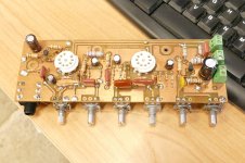
I made a simple test board that put a P-ch / N-ch mosfet pair on the cathode, control grid, and screen grid of a tiny Compactron sweep tube, the 6GF5. It's the ugly square board with a tube socket on both sides. Why both sides? Because the Big Dumm Blonde One screwed up and made the board backwards (swapped layers). I didn't figure it out until I fired it up and smoked several mostets. I only made one board, so I put parts on whichever side was electrically correct. Getting the "wrong" socket off without wrecking the board was too much work, so it stayed. I used this board and three different power supplies to hand draw tube curves of multiple different drive configurations.
Vacuum tube output stages use fixed bias, or cathode bias. fixed bias requires a negative voltage supply which adds cost, especially in a low buck amp. Cathode bias wastes power that could be sent to the speaker. I searched for a better way, and found that a mosfet in the cathode might be a way to recover that lost power without a negative supply. All experiments were done with the little 6GF5 tubes since I got 200 of them from Stan for cheap because "nobody ever bought any." The results were promising, until I tried a larger sweep tube, the 6HJ5. I had seen an early vintage Chinese KT88 spark out so violently that the glass shattered, but this was the first time I saw a vacuum tube EXPLODE scattering glass all over the place. After nearly trashing everything, I realized that the Big Dumm Blonde One screwed up the math and hit that poor tube with about 600 watts of dissipation.
Driving the cathode had been done before. It was common in ham radio RF power amps and even seen in a couple Music Man guitar amps using a BJT. Schade taught us that applying feedback from the plate of the tube to the grid makes triode curves with a pentode. His concepts usually involved feedback from the plate of the output to the plate of the driver to avoid DC blocking caps. If I need to elevate the cathode in order to drive it, I must also elevate the control grid, so I wound up with a simple two resistor divider. This avoided the issue of varying impedances when drying to stuff both the feedback and the drive into the control grid, and eliminated the need for a negative voltage supply.
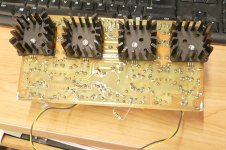
Those experiments led to a push pull amp that made 80 WPC with the small 6GF5 tubes. This was the first use of UNSET, without the SE. The ugly rats nest seen it pic #4070825 became a PCB in #4070828. The cathode mosfets are under the heat sinks on the back in the ratsnest and the PCB version.
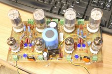
After making 80 WPC with tiny sweep tubes, I returned to where it all began, a low buck guitar amp that used old radio tubes for outputs. The green perf board proto contains a working power amp that makes 20 watts from a pair of 50C5 tubes running on an isolation transformer. I never finished the preamp section of this board because I had already made a PCB guitar preamp, so I simply wired it into the breadboard. The thread that sparked the UNSET design used a 50L6 which is a 6W6GT with a 50 volt heater that was common in old radios. The 50C5 and 50B5 are very similar tubes stuffed into a 7 pin bottle when radios got put on a cost and size diet. All are derived from the 6W6 which also spawned several other tubes. A pair of 6W6's in UNSET push pull will make 30 to 40 watts. The 50C5's will make 20 watts into 3300 ohms on 330 volts, which is easy to make from a cheap isolation transformer with my "way too many diodes power supply" seen on the right side of the breadboard. I have slowly been working on a PCB layout since I need a new guitar amp as i just gave mine to one of my grandsons.
Attachments


Thanks George!
I'm actually building an UNSET that will get some KT120 of a friend of mine, and will have the double feedback on driver's g1: from its own plate or from output transformer's plate, with bootstrapped load on the driver.
What I would like to implement on the UNSET is this feedback presented in 1933 by BAGGALLY at page 413 of Wireless Engineer:
https://worldradiohistory.com/UK/Experimental-Wireless/30s/Wireless-Engineer-1933-08-S-OCR.pdf
I've already used it in PP amps though a OPAMP to drive the other half of the phase splitter:
I scale down the output of the amp, subtract the input signal, amplify the result (there's a result only if there's distortion) and apply as feedback.
You get very high distortion reduction and damping factors, without affecting the sensitivity of the amp.
This in an UNSET would be great.
PCB design looking good I think.


Awaiting last component order to confirm all the footprints are correct, then off to JLC! Unless anyone can spot any errors or improvements to be made 👍
Awaiting last component order to confirm all the footprints are correct, then off to JLC! Unless anyone can spot any errors or improvements to be made 👍
Looks good indeed!
I'd review the copper fillings to make sure they don't create parasitic capacitances around high traces connected to impedance points
I'd review the copper fillings to make sure they don't create parasitic capacitances around high traces connected to impedance points
I wouldn't of thought there would be enough parasitic capacitance to meaningfully effect the performance of this circuit.
I know long tracks running parallel create capacitance, but I try to avoid that.
I know long tracks running parallel create capacitance, but I try to avoid that.
PCB's for power supply and preamp on order 😀 maybe 3 weeks? can't come quick enough.
Next will be testing and validating the power supply, then trying a few tweaks with the preamp board (BJT input, resistor value tweaks) to see what works best.
I'm hopeful for very low upper harmonic distortion 😉
The finished preamp has ended up bigger than I expected, looks like the case will be 400mm x 400mm, around 90mm tall. Built custom of course 👍
I submitted my last board to JLCPCB on Feb 19, got the PCBs on Feb 29. That's crazy!maybe 3 weeks?
- Home
- Amplifiers
- Tubes / Valves
- My custom tube preamp - Full build advice