Hi Raj,
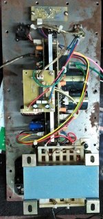
Vertically mounting. 5mm thick aluminium and 3 inch Hight,6.5 inch length
+/-75V 10A DC rail and FET used IRFP250N fsw@250KHz. OC protect @18A
Regards
MANOJ
Hi Manoj:
Is this version 3.0? So far I can recall your latest design was calibrated to work 500KHz.
Thanks
Raj
Is this version 3.0? So far I can recall your latest design was calibrated to work 500KHz.
Hi Raj,
yes ver 1.2 PCB and modified to ver 3.0
you can go up to 480KHz for this you need a good mosfet. i like 200-250KHz range it is good for old generation MOSFETs without any problem.
Regards
MANOJ
Hi Raj,
yes ver 1.2 PCB and modified to ver 3.0
you can go up to 480KHz for this you need a good mosfet. i like 200-250KHz range it is good for old generation MOSFETs without any problem.
Regards
MANOJ
Hi Manoj:
Can I use TL074 instead if 072&071? It will save pcb space and another free opamp can be used for protection.
Another issue, is it possible to replace 7404 & 555 with a micro controller?
Your comments are highly appreciated.
Thanks
Raj
Hi raj
i think micro controler is not fast enofe for porotection
CPX say to me this before
in class D amp we need a way that must be very fast to shutdown the mosfet driver IC and mosfets
sir manoj can help to you beter
have nice time my friend
i think micro controler is not fast enofe for porotection
CPX say to me this before
in class D amp we need a way that must be very fast to shutdown the mosfet driver IC and mosfets
sir manoj can help to you beter
have nice time my friend
Hi raj
i think micro controler is not fast enofe for porotection
CPX say to me this before
in class D amp we need a way that must be very fast to shutdown the mosfet driver IC and mosfets
sir manoj can help to you beter
have nice time my friend
After a long time Hadi!
Thanks for your reply. I was just wondering why an uC running @20MHz is not fast enough! to protect / trigger OC?
Besides, uC can also detect DC volts at Spk line without much component. This can be very good if uC is able to serve those purposes.
Thanks
Raj
hi my friend
i am so busy and i have many work for doing in my factory in last days off year
i am not electronic man
my best net friend CPX sayed to me the micro controler can not be fast enofe for doing protected
the dc voltage in amp out put is diferent voltage
some time 1 volt and some time 15 volt
new xmega can work with 3 volts and old 5 volts
what about AC volt in output of amp?
micro maybe damage
i dont test this before
i say before sir manoj can help you beter than me
have good day and do your job good and dont search the net bad boy when you are in work🙂
Last edited:
Hi Raj,Can I use TL074 instead if 072&071? It will save pcb space and another free opamp can be used for protection.
Another issue, is it possible to replace 7404 & 555 with a micro controller?
You cannot replace comparator(7404) with micro but you can use micro for DC,OC & TEMP protect,, ALC(limitter) also.
Regards
MANOJ
Hi Raj,
You cannot replace comparator(7404) with micro but you can use micro for DC,OC & TEMP protect,, ALC(limitter) also.
Regards
MANOJ
Thanks Manoj.
Can I use TL074 to replace 072&071?
Thanks
Raj
Hi ALL
AUD600 wired for SUB WOOFER RMS1400W@4R🙂🙂
EQ for aud600 wired 100Hz sub filter🙂🙂
Regards
MANOJ
Hi Manoj:
What would be the max output voltage at speaker line from AUD600? If given max rail voltage?
Thanks
Raj
What would be the max output voltage at speaker line from AUD600? If given max rail voltage?
Hi Raj,
i didn't check the speaker voltage,before filter its shows 16.2Vpp(supply +/-75V) square wave on DSO with 10x probe.
Regards
MANOJ
Hi Raj,
Transfomer AC Voltage is 53.1V and DC supply rail +/-71.5V current 10A volume level is up to clip indicator blinking point; check speaker voltage @27VAC. Clip indicator steady and bright point; speaker voltage @31.6VAC {speaker point connected 5R 50W resistor and it is too hot and burning smell coming tested @5min.}
from this you can calculate the out put watt
@27V AC means 27pp = 729W RMS @ clip point
@31.6V = 998W RMS
Regards
MANOJ
Last edited:
Class D amplifier with high performance and crystal oscillator
🙂 Good morning everyone.
My contribution to the forum.
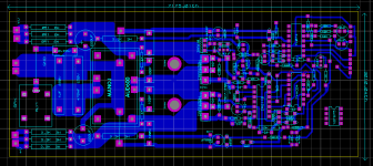
Have ridden with separate PCBs (clock / PWM audio input, power and protection).
I am now making a single PCB to finalize the project.
OK testing and operation.
Regards to all.
🙂 Good morning everyone.
My contribution to the forum.
Have ridden with separate PCBs (clock / PWM audio input, power and protection).
I am now making a single PCB to finalize the project.
OK testing and operation.
Regards to all.
Attachments

Member
Joined 2009
Paid Member
🙂 Good morning everyone.
My contribution to the forum.
Have ridden with separate PCBs (clock / PWM audio input, power and protection).
I am now making a single PCB to finalize the project.
OK testing and operation.
Regards to all.
thanks for the schematic luiz.
Looks interesting luizcpimenta, would be great to see some photos of your pcb when it's ready.
OK.
Hi luizcpimenta,
this is similar AUD1000C, thanks for new design. i will give you little correction for your design
1. Remove R129(1K5)
2. separate +15v supply for CD4060 for 12MHz switching it will take more current.
3. Re adjust R127 & R128 for PWM signal 3.3V level otherwise your Q103 will damage on long run(+B=75V or more)
Regards
MANOJ
Hi ALL
AUD600 wired for SUB WOOFER RMS1400W@4R🙂🙂
EQ for aud600 wired 100Hz sub filter🙂🙂
Regards
MANOJ
Hi Manoj:
I am trying to make a new PCB (AUD Ver3.0) with overload, DC protect and thermal protection. Basic AMP is taken from your schematic and protection will be controlled by micro-controller.
I need help for design the protection:
1. How much voltage needed to SD pin (IR2110) to trigger.
2. What will be the easier process to detect +ve over current as my micro will have +ve as its groound.
3. How to design/logic circuit to detect DC voltage at speaker line.
4. Can I use 12V BIAS voltage for relay and micro controller (5V with a regulator)
Thanks
Raj
Attachments
Last edited:
Hi luizcpimenta,
this is similar AUD1000C, thanks for new design. i will give you little correction for your design
1. Remove R129(1K5)
2. separate +15v supply for CD4060 for 12MHz switching it will take more current.
3. Re adjust R127 & R128 for PWM signal 3.3V level otherwise your Q103 will damage on long run(+B=75V or more)
Regards
MANOJ
Hi Manojtm.
I really relied on AUD1000 you sent me.
Thanks for the tips for my amplifier.
You have the files from AUD600 to send me?
Thank you again.
luizcpimenta@gmail.com
luizcpimenta@yahoo.com.br
- Home
- Amplifiers
- Class D
- My class D amp