Re: Re: V. 1.1
You are correct, just one of those those things that needed finishing. 🙂 Thanks for pointing that out. 🙂
rabstg said:
AC1 and AC2 appear to be hole through joining different top and bottom traces.
Or am I missing something?
I am NOT critiquing, merely stating...
You are correct, just one of those those things that needed finishing. 🙂 Thanks for pointing that out. 🙂
Attachments
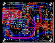
Troy, the colours melt together on the pic🙂 Its a bit hard to follow the traces. Russ, usually is quite safe, handling those rectifiers😉AC1 and AC2 appear to be hole through joining different top and bottom traces.
Yep. Use a MKT🙂 Physicaly, this board looks stuffed🙂Any chance to accommodate an even bigger input cap?
Steen😎
Nordic said:Any chance to accommodate an even bigger input cap? Erm, physicaly
22.5mm not big enough? 🙂 You can actually get a wide range of excellent 1-2uf MKPs in that size.
Anything bigger than that should probably be mounted directly at the input to save valuable PCB realestate.
Nordic said:Looked at MKP10's today, and they were about twice that...and only 0.47ufd
Keep looking 😉 Brian found some nice ones, but i forget the make/model. 🙂
Russ White said:
Absolutely there could be an appreciable difference, a layout indeed can make or break any circuit. In this case I seriously doubt the difference is huge, maybe not even detectable, but one would have to build both with the same parts and everything else being equal to know.
My only goal was to have people know which is which, since clearly the comparisons are not apples to apples.
Cheers!
Russ
Well once I get the Hypex UCD amp totally finished I'll build both Rudi's newer one and this newer one🙂 Its certainly more RevC amps than I need so I'll keep which ever one I like best and give the other two away
With every other amp I've built dual rectifiers have sounded better but I will try this one with singles
BTW theres plenty of 1uf MKP caps out there, some of the high voltage types with thick foils can sound poor especially with only a small amount of DC bias
Originally posted by Russ White [/ C version 1.1 based on new input from Mauro which has led to a few small tweaks for the PS (discrete rectifier diodes) and the input cap.
If there is interest I will share it.
Cheers and happy new year!
Russ [/B]
Russ,
Looking at this I see the discrete diodes, and it looks like the series input resistor is now 9.3K instead of 3.3K. Are there other changes that I have missed to this revised circuit?
Except for the diodes, I can make them to my still unstarted mono boards.
George
Hmm the input resistor is still 3.3K, in fact the entire circuit is exactly the same (Revision C) except for the new input cap and the discrete rectifiers. 🙂Panelhead said:
Russ,
Looking at this I see the discrete diodes, and it looks like the series input resistor is now 9.3K instead of 3.3K. Are there other changes that I have missed to this revised circuit?
Except for the diodes, I can make them to my still unstarted mono boards.
George
The layout is tweaked a lot though. I used a bunch of very cool trace calulators(thanks Mauro) to calulate trace heat, resistance, inductance, capacitance and RF frequencies, then I adjusted the PCB to get the values as close to optimal as I could right now. I am sure many could do better, but I am happy with it. 🙂
It is so easy to add an offboard recifier to this circuit that I did not bother to waste board space with double rectifers, as this qualifies as a ultra micro tweak. 🙂 Anybody who says they hear a major difference between single and dual rectifiers is probably one of those who also hears the sonic benefits of cable burn in. Frankly (though I don't wish to offend anyone) I just don't buy it. 😉 The change to a dual bridge PS is nothing earthshattering especially when PCB space is at a premium, which it is here. Yes, I have tried it, and no it did not impress me as any better at all, and it certainly would not warrant a change of the magnitude required to the layout. 🙂 But if you really want all those diodes, its easy enough to do. Just design a simple offboard PS and connect it with good wire to the amp PCB.
Most importantly I want the PCB to stay faithful to the schematic which Mauro designed. It is his amp. Those who want to can easily change all sorts of things even using this PCB. It is quite simple. The major changes to the PCB have originated from conversations with Mauro. I try not to project too much of my opinion onto his work. I try to let it speak for itelf, which it will, loud and clear. 😀
Cheers!
Russ
Well at least you did try dual rectifiers with dual secondarys
I'm actually amazed you did not hear any difference but thats fair enough😉
We all have our own opinions on this stuff
Yes, I also believe cable burn in makes no difference at all!
I'm actually amazed you did not hear any difference but thats fair enough😉
We all have our own opinions on this stuff
Yes, I also believe cable burn in makes no difference at all!
T. I would not go so far as to say that there "IS" no difference. Just that if there is (and I would say I am very critical) I cannot with honesty say it is "better". 🙂
I think that if you could hear a large effect from the dual/single bridge change then the rest of the PS would have to be, hmmm how should I say... designed not so well. 🙂
I think that if you could hear a large effect from the dual/single bridge change then the rest of the PS would have to be, hmmm how should I say... designed not so well. 🙂
Russ White said:T. I would not go so far as to say that there "IS" no difference. Just that if there is (and I would say I am very critical) I with honesty say it is "better". 🙂
I think that if you could hear a large effect from the diode change then the rest of the PS would have to be, hmmm how should I say... designed not as well. 🙂
Well it seems to me some people are wanting to get the best out of the amp, even a small difference is still a difference😉
If your happy with it then thats fine, I've built more than enough amps to know the difference between a well designed psu and a not so good one
t. said:
Well it seems to me some people are wanting to get the best out of the amp, even a small difference is still a difference😉
Very true, and if I (and others) thought there was even a detectable advantage I might be tempted to implement the change to dual bridges. The thing is I will not let my notion of "better" hold sway over what is already known to be superb. It certainly "aint broke" so there is nothing to be "fixed".
"better" in audiophile terms is truly a personal and subjective formula, and does not necessarily equate (actually almost never does) from person to person. 🙂 So I accept your view, I just don't think that in this case the change is warranted.
In any case, yes I have tried dual bridges even with dual trafos(not just dual secondaries though I tried that too), and no, like a myriad of other things it does not make the cut, not because it does not work well (I would say even very well), but because well... more is not always better. 🙂
Yes, I too have come to rcognize good PS design, but I also know I have a lot to learn. This is one of those great simple designs, in fact I would say part of its greatness is its simplicity.
In short, this is not going to be a new amp, it is Mauro's design, and I for one am a pleased with it as is. I really doubt I could ever get much more out of it than it can already give. To do so you would have to radically change the circuit. Say new power devices.... hmmmmmmm.... 😉
Cheers!
Russ
Russ White said:Nordic, sounds like he has speakers which need much more power than MyRef can deliver.
...
This is a limitation of the LM3886 and the circuit, it would not matter which PCB,rectifier,PS, etc.. you used.
Russ, don't blame the LM3886 chip, because it can sound surprizingly good and drive speakers that you would never thought possible.
In this design there's a 0.47R resistor in series with the output, this does no favours.
Also, serious (and tight) bass IME starts at around 20,000uF capacitance per rail (unregulated), and some more is even better, or a regulated PSU.
This is not a critic at all, it's just that this implementation has some particularities, it will not drive difficult speakers. And difficult speakers are aplenty these days.
Carlos, I am not "blaming" anything. Just facing facts. It is this circuit and its implementation of the LM3886 which I said could not handle the load. The sense resistor is a necessary part of the design so I would not say it is a bad thing. 🙂 The only speakers I have had issues with using this design are pretty inefficient. Also you have to take everything with the view that you never know what conditions things were tested in, nor really how the amp being tested was executed or setup. 🙂 There are many variables.
I regularly drive my 4ohm three ways to levels which the neighbors would consider way too loud. 🙂 So I am confident in the amps abilities to drive most speakers. I am sure there are others with similiar experience.
Nice to see you BTW I hope you are well. Happy new year.
I regularly drive my 4ohm three ways to levels which the neighbors would consider way too loud. 🙂 So I am confident in the amps abilities to drive most speakers. I am sure there are others with similiar experience.
Nice to see you BTW I hope you are well. Happy new year.
Russ White said:The sense resistor is a necessary part of the design so I would not say it is a bad thing. 🙂
I'm not saying it's a bad thing, and I know it's part of the design. But the amp has higher output impedance, which reduces damping factor.
So, the amp can't drive difficult speakers, and it doesn't have anything to do with 'inefficient' speakers, bacause sensitivity just says how loud can the speakers play.
There are 8 ohm speakers that are much harder to drive than some 4 ohm desigs, and there are low sensitivity speakers that are a light load to an amp.
Sure Carlos ou and I are in complete agreement on the point. There are many speakers which are 8ohm nominal but can dip well below 2ohm impedance at certain frequncies. Speaking as someone who has built just about every chipamp topology under the sun I can say there are some speakers which simply will not be driven effectively by any LM3886 circuit. That is a simple fact. 🙂
That being said I have no idea what happened or why in Nordic's test, nor does anyone else, so nobody should "blame" anything. There is not enough data to make the critical analysis.
That being said I have no idea what happened or why in Nordic's test, nor does anyone else, so nobody should "blame" anything. There is not enough data to make the critical analysis.
Russ White said:...I can say there are some speakers which simply will not be driven effectively by any LM3886 circuit. That is a simple fact. 🙂
I didn't say that a single LM3886 chip will drive any speaker.
I just said that this implementation does not take the LM3886's driving abilities (single chip) to the max. It was not intended to, anyway.
Look at the datasheet, the LM3886 almost doubles the power figure with a 4 ohm load.
carlosfm said:
Look at the datasheet, the LM3886 almost doubles the power figure with a 4 ohm load.
You think I have not? 😉 Yes almost every conventional amp's output power is inversly proportional to the load impedance. 🙂
There were a few images throughout this thread where folks have used metallised polyprops as input caps. Just want to report that I've done the same thing, using TP boards.
C13 (1uF wima) was replaced with a 1.5uF auricap. C9 (220uF FC) was replaced with a same value standard black gate. Both were done at the same time so I have no idea if one is more beneficial than the other. The changes were certainly beneficial though.
There was some harshness, mostly the upper mids and higher, to the sound that has been curbed. Soundstage has improved consideraby. The amp is just a nicer listen all round. I wasn't actually expecting a lot to change but it did and was well worth it.
I'd do it again but as always, ymmv.
Mauro pic
I slightly prefer the use of an active (opa627) pre but it's a marginal preference. Granted the pot is after the 627 which isn't ideal and is something that'll be rectified when the amp is put in a new case in power amp configuration. It was originally integrated as you can see from the pic.
Cheers
Kendal
C13 (1uF wima) was replaced with a 1.5uF auricap. C9 (220uF FC) was replaced with a same value standard black gate. Both were done at the same time so I have no idea if one is more beneficial than the other. The changes were certainly beneficial though.
There was some harshness, mostly the upper mids and higher, to the sound that has been curbed. Soundstage has improved consideraby. The amp is just a nicer listen all round. I wasn't actually expecting a lot to change but it did and was well worth it.
I'd do it again but as always, ymmv.
Mauro pic
I slightly prefer the use of an active (opa627) pre but it's a marginal preference. Granted the pot is after
the 627 which isn't ideal and is something that'll be rectified when the amp is put in a new case in power amp configuration. It was originally integrated as you can see from the pic.Cheers
Kendal
- Home
- Amplifiers
- Chip Amps
- My "audiophile" LM3886 approach