The factons provided with the Rev C kits will take 15 AWG (1.45mm dia) wire, which I agree is sufficient for the short runs needed.
It's what I am using for the short 25V AC supply wires, and something similar for the case speaker wires.
Small section (around 1mm/18ga or a little larger) solid core wire was/is preferred by some as speaker wire, though I would not use it with higher powered amps.
Audie.
It's what I am using for the short 25V AC supply wires, and something similar for the case speaker wires.
Small section (around 1mm/18ga or a little larger) solid core wire was/is preferred by some as speaker wire, though I would not use it with higher powered amps.
Audie.
Also, you can easily find other female fastons that take up to 10ga wire if you really want them.
Fixed mine today!!!!!!!!!!!
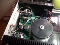
Finally got tired of searching for the cause of an intermittant +32 volts on the output of my Rev C. Set in up out of the chassis with heatsinks to allow checking voltages. Up till today I had done all checking while mounted in a real tight box.
Once the relay clicked outhe voltage on one channel was back. Found even that there was 32 volts on the output, there was only 0.1 volts on the 220 ufd feebback cap. So followed it to the 12K feedback resistor. Touching both ends with a iron has solved this problem.
The amp had been running trouble free for months. The intermittant problem occured after a couple hundred hours use.
I was ready to swap out the LM3886, LM318, and the zeners to try and get it working again. Glad I didn't. That would have been a wasted 5 - 10 hour job that did not fix anything.
For anyone else getting a bunch of voltage on the outputs, check the feedback loop. An open in it resulted in almost the full positive rail voltage on the output for that channel.
George
panelhead,
I can see how such a problem could easily happen. Good to hear you've solved the problem.
I only just started on my rev c boards. I have a good Royel DC Temp controlled soldering station with a small chisel tipped 40W iron and am having trouble getting heat to the track and component using Wonder silver content solder. Only soldered a few small resistors so far, including R7 that you mentioned.
Checked them with a magnifying glass, and will need to redo a few.
I think better to be sure from the start to save problems later, though it takes a lot longer. I still wouldn't guarantee my work though- maybe I will fry a component in the process, even though I'm using freezer spray and a small heat sink clamp when able.
All the best for the new year.
Audie.
How are you using the freezer spray? Also, does the winder solder have a rosen core? If not, you will need to use a liquid rosen. I'm not sure of the temps for that solder, so I cannot comment on that. I have soldered about 10 of these boards up using standard solder and have not had any issues.
Multi-core is the minimum audiofile quality solder, the 402 and 405 are fabulous.
I also have the wonder silver solder. After using it once I gave it to Repute. It just doesn't work as well as the Multicore.
Side note, even with Multicore I still use Keester paste rosin flux.
I also have the wonder silver solder. After using it once I gave it to Repute. It just doesn't work as well as the Multicore.
Side note, even with Multicore I still use Keester paste rosin flux.
Thanks for the replies.
TRT Wonder solder is a resin core silver content solder that has been long recommended by the audiophile community, so that's why I have it.
As rabstg found, it does not seem to work as well as normal multi-core.
I'll first try using some additional resin paste, and if still not satisfactory will use plain old resin-core.
Brian,
Where I cannot get a heatsink clamp on the component I give the component a squirt of the freezer spray before soldering.
I reason that it is the leads I want to heat up-not the component.
The less the component heats up the better.
Audie.
Hi all--- another question I need help with:
I understand the TP boards are double-sided with mounting holes through-soldered.
This is the first double-sided board I've worked with (being born in the last century), so am wondering why the boards I've seen posted have the small components soldered on the component side.
Shouldn't it only be necessary to solder on the non-component side, considering the holes are through-soldered?
Soldering on the component side is difficult, and with the small clearances between traces, bridging is possible.
Audie.
You can solder the components on either side, what ever is easier for you. With through-hole, you want to let the soldering iron heat the board and component pin for a few seconds before applying the solder.
I would be careful with the freezer spray, as a big temp differential can also cause damage to the components (very cold to very hot, ver quickly). I have never used it and not had any problems. Most components can take the heat of soldering without damage for a good 10 seconds or so (each component is rated differently and you can usually find something in the datasheet about how long and what temp they can withstand).
I would be careful with the freezer spray, as a big temp differential can also cause damage to the components (very cold to very hot, ver quickly). I have never used it and not had any problems. Most components can take the heat of soldering without damage for a good 10 seconds or so (each component is rated differently and you can usually find something in the datasheet about how long and what temp they can withstand).
Thanks Brian,
I soldered the first 6 small resistors both sides - to be sure.
Now I will do it in what looks like the easy way, and solder on the non- component side, and save a lot of effort.
Audie.
I soldered the first 6 small resistors both sides - to be sure.
Now I will do it in what looks like the easy way, and solder on the non- component side, and save a lot of effort.
Audie.
Oh. I thought you were asking about placing the components on the non-components side.
You can solder just on the non-components side. That's al you need to do. Sorry, misunderstood the question.
You can add more solder to the components side, but you really don't need to.
You can solder just on the non-components side. That's al you need to do. Sorry, misunderstood the question.
You can add more solder to the components side, but you really don't need to.
Just a thought/suggestion regarding "second' side soldering on through holes:
Save it until several components are mounted and before the component side gets congested, then do it as part of a final inspection.
Save it until several components are mounted and before the component side gets congested, then do it as part of a final inspection.
I typically solder all the components from the bottom then flip over the board and reheat the lead as I inspect each solder to let gravity pull the excess down the lead before clipping the lead short.
This way all solder joints are "flush" with the top of the board with next to no chance of solder bridges on the top.
This way all solder joints are "flush" with the top of the board with next to no chance of solder bridges on the top.
The KTA -"kitchen table amp"....
This is my first post to this forum, although I was lurking in the background for quite a while. After having completed the Twisted Pair MyRef_C kit some time ago, I think it is about time to give this thread a bit of momentum back, or let’s say positive energy! I was tempted to build the MyRef_C amp because the usual GC iterations start to get really boring to look at, if not to listen to (uhoh!)... Recently I do see some MyRef_C builds suffering from assembly/soldering problems – so I can simply reconfirm this amp has worked flawlessly from the very first second after power up – no DC offset issues, switch on thumps and/or other nasty things to deal with.
A big thanks to Mauro Penasa to offer his brilliant design to the DIY community. It detours some of the usual pitfalls seen with several GC variants, yet this isn’t a gainclone - - but stunningly – I think it brings out the best the LM3886 chip has to offer sonically..... Further praises definitely go to Russ and Brian for their RevC kit offering, which can be considered to be complete, as well as quick and easy to whip up.
Here we go:
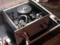
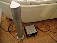
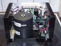
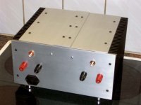
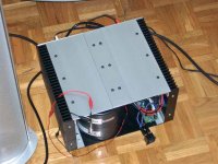
The heatsinks I have chosen, which are an integral part of the “enclosure design”, are somewhat overdimensioned not only to sustain good cooling. The sinks feature 25 x 15 x 3cm dimensions since I wanted to go for a small footprint amp with less than the width and depth of commercial 19” rack type enclosures. The taller build structure looks better for my eyes, and was necessary because I wanted to deploy two 300VA trannies. As for the parts changes that deviate from the TP kits, I used Rubycon ZA 220uF as C19 feedback caps (slightly lower E.S.R. than Panasonic FCs). Since Russ’s PC board design was optimized for a small footprint, I went along to have the input coupling capacitor mounted externally, just to be able to mount something physically larger than a standard 1uF MKT/MKP. In the end I settled for a Siemens MKV type, I had those lying around anyway.... Furthermore the amp houses an LC Audio inrush current limiter and a small perfboard, that carries a ground loop breaker circuit (two diodes, a 10R resistor and a 0.1uF 400V cap).
Everything else is pretty much standard as delivered with the TP kits. As with most amps and preamps, the mechnical work involved is the most challenging and time consuming part.
One thing to mention: I had to route wires from my ground breaker circuit to the P-GND terminals on the PCB, to get the amp quiet. It had a clearly audible and annoying ground loop induced hum without this connection.
So as for those that still wonder how the MyRef_C sounds, I can keep it short: Stunning! Tonal balance is neutral with good bass extension and balanced treble – while one thing really impresses me the most: The sound stage is huge and totally stable, with pinpoint accuracy (the often misused word “palpable” comes to mind...).
Cheers
Andre
PS: The front plate is not on yet, because it needs to be chopped off on top and it is 12mm thick on the sides....
This is my first post to this forum, although I was lurking in the background for quite a while. After having completed the Twisted Pair MyRef_C kit some time ago, I think it is about time to give this thread a bit of momentum back, or let’s say positive energy! I was tempted to build the MyRef_C amp because the usual GC iterations start to get really boring to look at, if not to listen to (uhoh!)... Recently I do see some MyRef_C builds suffering from assembly/soldering problems – so I can simply reconfirm this amp has worked flawlessly from the very first second after power up – no DC offset issues, switch on thumps and/or other nasty things to deal with.
A big thanks to Mauro Penasa to offer his brilliant design to the DIY community. It detours some of the usual pitfalls seen with several GC variants, yet this isn’t a gainclone - - but stunningly – I think it brings out the best the LM3886 chip has to offer sonically..... Further praises definitely go to Russ and Brian for their RevC kit offering, which can be considered to be complete, as well as quick and easy to whip up.
Here we go:
The heatsinks I have chosen, which are an integral part of the “enclosure design”, are somewhat overdimensioned not only to sustain good cooling. The sinks feature 25 x 15 x 3cm dimensions since I wanted to go for a small footprint amp with less than the width and depth of commercial 19” rack type enclosures. The taller build structure looks better for my eyes, and was necessary because I wanted to deploy two 300VA trannies. As for the parts changes that deviate from the TP kits, I used Rubycon ZA 220uF as C19 feedback caps (slightly lower E.S.R. than Panasonic FCs). Since Russ’s PC board design was optimized for a small footprint, I went along to have the input coupling capacitor mounted externally, just to be able to mount something physically larger than a standard 1uF MKT/MKP. In the end I settled for a Siemens MKV type, I had those lying around anyway.... Furthermore the amp houses an LC Audio inrush current limiter and a small perfboard, that carries a ground loop breaker circuit (two diodes, a 10R resistor and a 0.1uF 400V cap).
Everything else is pretty much standard as delivered with the TP kits. As with most amps and preamps, the mechnical work involved is the most challenging and time consuming part.
One thing to mention: I had to route wires from my ground breaker circuit to the P-GND terminals on the PCB, to get the amp quiet. It had a clearly audible and annoying ground loop induced hum without this connection.
So as for those that still wonder how the MyRef_C sounds, I can keep it short: Stunning! Tonal balance is neutral with good bass extension and balanced treble – while one thing really impresses me the most: The sound stage is huge and totally stable, with pinpoint accuracy (the often misused word “palpable” comes to mind...).
Cheers
Andre
PS: The front plate is not on yet, because it needs to be chopped off on top and it is 12mm thick on the sides....
Attachments
- Home
- Amplifiers
- Chip Amps
- My "audiophile" LM3886 approach