G.Kleinschmidt said:The correction voltage is well under 2V at the onset of curent limmiting at 64A. Most is this voltage drop is produced across the emitter ballast resistors for the output transistors, which do not adversely effect the linearity.
Sorry, I should have said 4V.
The actual EC circuit runs out of headroom at about 5.7V.
So, at the rated output power of 1kW RMS into 2 ohms (giving ~32A peak) there is heaps of headroom.
Cheers,
Glen
Hi Glen,
The Lightstar was rated at 1200W RMS into 2 R per channel, and rated to handle impedance variations. It used a bank of 6-2SC3281 and 6-2SA1302 for each channel. We did have problems with the 1 W feedback resistor burning out. The amplifier required a pair of 15A circuits (20 A recommended) to deliver this power. So this was 1200 W into 2 R at it's rated distortion, not clipping. The high frequency "down converter was well filtered and did not inject switching hash into the output. Each channel ran off it's own power supply and each down converter was shielded from the rest of the amp.
So it would seem the thing you've never heard of was available years ago commercially. I had one for a while and it worked very well. Just the case for a heatsink, no fins were required.
Carver has already done what you set out to do, you simply want to use a different main amp topology. It would seem to me that you shouldn't dismiss things so easily in the future.
Again, Carver found the switching supply to be more responsive, more reliable with less noise transmitted to the output than the so called "more linear class B amplifier". Carver used the class B type for years and years before changing over to the switching supply, or down converter as it is used in the Lightstar. I can tell you that this is true from my own direct experiences with these in service.
-Chris
Time for you do do some homework.A switching amplifier suffers from non linearities other than clock frequency hash on the output. They are just not as linear as a class B amplifier. I don't know much about Carver amps, but I'm sure I've never seen one rated at 1kW RMS continuous sinewave per channel with peak output currents of 64A.
The Lightstar was rated at 1200W RMS into 2 R per channel, and rated to handle impedance variations. It used a bank of 6-2SC3281 and 6-2SA1302 for each channel. We did have problems with the 1 W feedback resistor burning out. The amplifier required a pair of 15A circuits (20 A recommended) to deliver this power. So this was 1200 W into 2 R at it's rated distortion, not clipping. The high frequency "down converter was well filtered and did not inject switching hash into the output. Each channel ran off it's own power supply and each down converter was shielded from the rest of the amp.
So it would seem the thing you've never heard of was available years ago commercially. I had one for a while and it worked very well. Just the case for a heatsink, no fins were required.
Carver has already done what you set out to do, you simply want to use a different main amp topology. It would seem to me that you shouldn't dismiss things so easily in the future.
Again, Carver found the switching supply to be more responsive, more reliable with less noise transmitted to the output than the so called "more linear class B amplifier". Carver used the class B type for years and years before changing over to the switching supply, or down converter as it is used in the Lightstar. I can tell you that this is true from my own direct experiences with these in service.
-Chris
Originally posted by G.Kleinschmidt I don't know where Bob got the low voltage idea from. The EC circuit Bob modified slightly for his MOSFET amp was originally designed by Hawksfors and described in his paper for Darlington BJT output stages.
I'm using a different EC circuit (figure 4 in Hawksford's paper) to do something different.
I'm not sure either.
I have the original AES journal article and it clearly shows BJTs.
But since you're working on an amp, I thought I'd ask.
anatech said:Hi Glen,
Time for you do do some homework.
The Lightstar was rated at 1200W RMS into 2 R per channel, and rated to handle impedance variations. It used a bank of 6-2SC3281 and 6-2SA1302 for each channel. We did have problems with the 1 W feedback resistor burning out. The amplifier required a pair of 15A circuits (20 A recommended) to deliver this power. So this was 1200 W into 2 R at it's rated distortion, not clipping. The high frequency "down converter was well filtered and did not inject switching hash into the output. Each channel ran off it's own power supply and each down converter was shielded from the rest of the amp.
So it would seem the thing you've never heard of was available years ago commercially. I had one for a while and it worked very well. Just the case for a heatsink, no fins were required.
Carver has already done what you set out to do, you simply want to use a different main amp topology. It would seem to me that you shouldn't dismiss things so easily in the future.
Again, Carver found the switching supply to be more responsive, more reliable with less noise transmitted to the output than the so called "more linear class B amplifier". Carver used the class B type for years and years before changing over to the switching supply, or down converter as it is used in the Lightstar. I can tell you that this is true from my own direct experiences with these in service.
-Chris
I am not dismissing the worth of switching amplifiers, I am simply giving my reasons for choosing a linear class B amplifier - mostly to do with the fact that I am aiming for very low THD and noise.
My amplifier is rated at 1000W RMS CONTINUOUS SINEWAVE into 2 ohm in CLASS A, with the output current limited to 64A for driving 1 ohm loads for brief periods at 2kW RMS class AB.
I doubdt that the Lightstar came close to this, even with its 1200W RMS rating. And was the Lightstars 1200W RMS in class A?
Also, I am aiming for typical THD figures at 1kW per channel in the ppm range - I really doubdt that the Lightstar amplifer was anything close to this. Do you have the THD figures?
I've done a quick goolgle on the "Lightstar", but I havent found anything conclusive on how its works. You say that the Lightstar idled with rails of +/-13V - If this is the case then it cannot possibly be a class A amplifier (unless it was a very big amplifier, since it only used the case for a heatsink) - Which is what I am buliding (Hence the need for the big heatsinks).
1200W RMS into 2 ohms = 69.3V peak = 34.7A peak.
A class A output stage would require a bias current of 17.3A. At +/-13V, that's 450W of idle dissipation, or 900W for a stereo amplifier.
My design runs an idle if 16A for 1kW RMS Class A into 2 ohms with rails for the class A stage of only +/-7V.
Another thing which makes my design unsuitable for a class D is the fact the the class A output bias current of 16A would have to be supplied by the switching amplier - and this still wouldn't do anything for the class A idle dissipation.
I think that my design and the Lightstar are completely different beasts, with rather different design goals.
Cheers,
Glen
Hi Glen,
As I stated before, supply noise was far lower using a switching down converter. The Class B commutators used in earlier Carver products put a tiny "pip" on the output waveform. I did check these things.
So, again, the high frequency switching tracking supply injected much lower noise into the signal. I couldn't detect any, but I'll refrain from say it injected no noise. I could clearly see the transients on the class B rail control.
I really don't see how this matters. If you can get the same quality at a lower current, it would seem to me that you would run lower current. I do know for sure that the cooler something runs, the longer it will last. But I am not here to cut up you design, I was only trying to help you out.
Anyway, try to think about these things a little. It may help you with your heat issues.
-Chris
Top rails on the Lightstar are + - 125 VDC.My amplifier is rated at 1000W RMS CONTINUOUS SINEWAVE into 2 ohm in CLASS A, with the output current limited to 64A for driving 1 ohm loads for brief periods at 2kW RMS class AB.
It easily surpassed this. I don't know why you doubt things so much.I doubdt that the Lightstar came close to this, even with its 1200W RMS rating.
As I stated before, supply noise was far lower using a switching down converter. The Class B commutators used in earlier Carver products put a tiny "pip" on the output waveform. I did check these things.
So, again, the high frequency switching tracking supply injected much lower noise into the signal. I couldn't detect any, but I'll refrain from say it injected no noise. I could clearly see the transients on the class B rail control.
Yes, and as I stated, at or below the rated distortion. The class A doesn't have any bearing on the statement. It ran with approximately a 13 volt differential between signal and supply. At idle the supplies sat between 12.5 VDC and 13.5 VDC. Full voltage was 125 VDC. I can tell you that the bias current was higher than normal. The case got very warm sitting there doing nothing. It didn't get that much warmer when pounding. It was, a very big amplifier (80 lbs I think). Around the same weight as a Marantz 500.And was the Lightstars 1200W RMS in class A?
Not any more. They weren't that important really once you get above a certain level of quality.Do you have the THD figures?
So if you are running at +/- 7V class A, I really don't understand why the design wouldn't work with +/- 13 V rails. What on earth am I missing here? You can't be worried about dissipation if you plan to run 7 amperes class A all the way up to 69.3 V supply peak.My design runs an idle if 16A for 1kW RMS Class A into 2 ohms with rails for the class A stage of only +/-7V.
I really don't see how this matters. If you can get the same quality at a lower current, it would seem to me that you would run lower current. I do know for sure that the cooler something runs, the longer it will last. But I am not here to cut up you design, I was only trying to help you out.
Okay,now you have me so completely lost as to your point here. Class B will cause so much more energy to be dissipated as heat than a switching supply it's not funny. Not class D, a switcher. The dissipation of the amplifier stage would be the same either way. This is a non-issue when looking at supply losses.Another thing which makes my design unsuitable for a class D is the fact the the class A output bias current of 16A would have to be supplied by the switching amplier - and this still wouldn't do anything for the class A idle dissipation.
Anyway, try to think about these things a little. It may help you with your heat issues.
-Chris
I'll probably come over and fry up some breakfast on those heatsinks when your massive amp is finished.....
What kind of thd figures are you aiming for?
What kind of thd figures are you aiming for?
anatech said:Hi Glen,
Top rails on the Lightstar are + - 125 VDC.
It easily surpassed this. I don't know why you doubt things so much.
As I stated before, supply noise was far lower using a switching down converter. The Class B commutators used in earlier Carver products put a tiny "pip" on the output waveform. I did check these things.
So, again, the high frequency switching tracking supply injected much lower noise into the signal. I couldn't detect any, but I'll refrain from say it injected no noise. I could clearly see the transients on the class B rail control.
Yes, and as I stated, at or below the rated distortion. The class A doesn't have any bearing on the statement. It ran with approximately a 13 volt differential between signal and supply. At idle the supplies sat between 12.5 VDC and 13.5 VDC. Full voltage was 125 VDC. I can tell you that the bias current was higher than normal. The case got very warm sitting there doing nothing. It didn't get that much warmer when pounding. It was, a very big amplifier (80 lbs I think). Around the same weight as a Marantz 500.
Not any more. They weren't that important really once you get above a certain level of quality.
So if you are running at +/- 7V class A, I really don't understand why the design wouldn't work with +/- 13 V rails. What on earth am I missing here? You can't be worried about dissipation if you plan to run 7 amperes class A all the way up to 69.3 V supply peak.
I really don't see how this matters. If you can get the same quality at a lower current, it would seem to me that you would run lower current. I do know for sure that the cooler something runs, the longer it will last. But I am not here to cut up you design, I was only trying to help you out.
Okay,now you have me so completely lost as to your point here. Class B will cause so much more energy to be dissipated as heat than a switching supply it's not funny. Not class D, a switcher. The dissipation of the amplifier stage would be the same either way. This is a non-issue when looking at supply losses.
Anyway, try to think about these things a little. It may help you with your heat issues.
-Chris
I think that I have given this design a great deal more thought than you have.
You answer “yes” to my question regarding if the Lightstar is rated at 1200W RMS into 2 ohms in CLASS A, and then just tell me that it had a higher bias current “than normal”.
I have already given you the dissipation figures for such a case. You inform me that the Lightstar has tracking rails of +/-13V. If the Lightstar really is rated to 1200W into 2ohms in pure class A, then its idle current will be in the order of 17A and dissipation is in the vicinity of 900W – roughly DOUBLE that of my design which has tracking rails of only +/-7V for the power stage driving the speaker. I don’t know where you get the idea that I am planning to run a bias current of 7A from either – It’s 16A.
The preference of running tracking supply rails of a voltage significantly lower than +/-13V for class A operation should be obvious.
The idea that a switching amplifier should be intrinsically less noisy than a Class B amplifier is a technical furphy which I would expect from a marketing department. Also, I suggest that you do not confuse crossover artefacts on the tracking supply rails with noise. With regards to the feed through of crossover artefacts on the tracking supply rails, I refer you to the mathematical analysis contained in the AES CLASS A+ paper linked to earlier. I have also chosen Hawksford Error Correction for my class A output stage to address this issue. Did the Lightstar have EC applied to the output stage? If you can provide a good technical analysis of why my class A EC scheme is flawed, I’d really like to hear it.
I asked you for the THD and noise figures of the Lightstar because they are pivotal to my chosen topology. You simply dismiss them, as well as the chosen class A bias as irrelevant. They are not irrelevant. I suggest that you read my (and the few others) previous postings on the workings of the Class A+ topology. I don’t think that you fully realise exactly what I am endeavouring to construct here.
Any yes, a switching amplifier for the tracking rails will of course dissipate much less power than a class B amplifier. My point was that a switching amplifier driving the rails would not lower the idle dissipation of the class A core which, under normal operating conditions, contributes the majority of the power dissipated.
Hi Glen,
We agree on some things and appear not to agree on others, when in fact we might.
I've been giving the whole tracking supply idea a lot of thought since I started working on Carver product. That is a really long time.
Anyway, I was trying to give you some helpful ideas that you are intend on shooting down because you are fending off a non-existent attack. Not from me at any rate. Enough for me.
-Chris
anatech said:Hi Glen,
We agree on some things and appear not to agree on others, when in fact we might.
I've been giving the whole tracking supply idea a lot of thought since I started working on Carver product. That is a really long time.
Anyway, I was trying to give you some helpful ideas that you are intend on shooting down because you are fending off a non-existent attack. Not from me at any rate. Enough for me.
-Chris
Chris, I'm not trying to shoot down your ideas. I'm simply trying to put across that I have chosen the design path I have for valid reasons.
The Lightstar does sound like an interesting design and I think that a swticher for the tracking rails would be a valid approcach for some design specifiactions, but not mine.
I am building an overtly esoteric amplifier where power dissipation is of secondary importance to the performance objectives. Even with all the power dissipated by my design, with those over-the-top heatsinks, it will still run relatively cool. 😎
With the THD+noise performance I'm hoping to achieve, a switcher as an anathema.
Also, amongst the compliments and encouragements, there are numerous blithe dismissals and criticisms (I’m not saying from you) of the topology I have chosen throughout this thread, most with very little technical substantiation. This puts me into a snooty mood.
It would be nice to see a few of the critics submit an equally ambitious and self-funded DIY project.
Cheers,
Glen
Are you speaking about plain class B single-tier cascoding, or about multiple-tier class H/class G cascoding?
Concerning switching amplifiers employed as "rail cascodes", have you ever taken a look at self oscillating modulators and the resulting THD figures?
Hint: http://www.ciaudio.com/ucd_aes.pdf
Concerning switching amplifiers employed as "rail cascodes", have you ever taken a look at self oscillating modulators and the resulting THD figures?
Hint: http://www.ciaudio.com/ucd_aes.pdf
Eva said:Are you speaking about plain class B single-tier cascoding, or about multiple-tier class H/class G cascoding?
Neither. A floating low power supply for the class A output stage driven to linearly track the output with a completely separate class B amplifier (Optimally biased class B in my design – which some like call AB, despite what D.Self says) with it’s own feedback loop and driven with the same input signal as the class A amplifier.
No switching involved.
Reference linked to from here (unfortunately you have to pay for it):
http://www.diyaudio.com/forums/showthread.php?postid=1237267#post1237267
Eva said:Concerning switching amplifiers employed as "rail cascodes", have you ever taken a look at self oscillating modulators and the resulting THD figures?
Hint: http://www.ciaudio.com/ucd_aes.pdf
[/B]
That Bruno Putzeys amplfier has outstanding THD performance for a switching amplifier. I regard Bruno to be one of the best switching amplifier designers out there.
Hint: But his design is rated at only 100W. My design is rated at 1kW with a peak output current of 64A (2kW for brief bursts into 1 ohm)
Please give me a switching design of comparative power output which is as easy to implement and can perform as well as one easily built using a linear output stage. Have you ever designed one?
G.Kleinschmidt said:It would be nice to see a few of the critics submit an equally ambitious and self-funded DIY project.
Nagging comes free of charge.
Feedback loops won't be separate at all at high frequencies due to miller capacitances. The open loop phase lag of both amplifiers will add up and will force you to use much less NFB to achieve stability, resulting in higher THD and lower gain bandwidth product. The only way to circumvent this that I know involves reducing the slew rate of the class B tracking amplifier considerably.
Do you have any experience with nested feedback? Have you done any control loop modelling in PSpice? Have you done any lower power prototyping (like a 25W version of your idea in a breadboard...)? This should be the starting point.
Do you have any experience with nested feedback? Have you done any control loop modelling in PSpice? Have you done any lower power prototyping (like a 25W version of your idea in a breadboard...)? This should be the starting point.
Eva said:Feedback loops won't be separate at all at high frequencies due to miller capacitances. The open loop phase lag of both amplifiers will add up and will force you to use much less NFB to achieve stability, resulting in higher THD and lower gain bandwidth product. The only way to circumvent this that I know involves reducing the slew rate of the class B tracking amplifier considerably.
Do you have any experience with nested feedback? Have you done any control loop modelling in PSpice? Have you done any lower power prototyping (like a 25W version of your idea in a breadboard...)? This should be the starting point.
My idea?
You obviously have not actually read the AES paper I linked to describing the Technics patent. This is not my idea, it is a proven design topology developed Technics in the late 70’s.
I really can't make sense of what you are trying to say. If the slew rate of the class B amplifier is reduced relative to the class A amplifier then the class B driven floating rails (which are only for the class A output devices) will not track the output voltage on fast transients. And I really can't see how the "miller capacitances" (please don't be too specific here) can cause the symptoms you describe.
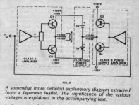
Pictured below is a simplified block diagram of the high power amplifier Technics manufactured using this technique – the global negative feedback for each separate amplifier was not curtailed in the least.
A much better diagram showing the GNFB connections of each seperate amplifier exists in the AES paper, along with a thorough explanation and performance measurements of a prototype amplifier.
Here is the title and a link to the AES paper again:
"High Efficiency Class A Audio Power Amplifier"
(CLASS A+ AMPLIFIER)
AES Preprint no. 1382 (N-5)
Presented at the 61st Convention
November 3-6, 1978
http://www.aes.org/e-lib/browse.cfm?elib=2972
Attachments
The concept could be implemented using switching-mode:
http://www.diyaudio.com/forums/showthread.php?threadid=73465
http://innovexpo.itee.uq.edu.au/2003/exhibits/s354194/
http://www.ece.uvic.ca/~ece499/2005b/group09/Docs.htm
http://www.itee.uq.edu.au/~walkerg/publications/_others/ertl_kolar_zach_smala.pdf
http://www.diyaudio.com/forums/showthread.php?threadid=73465
http://innovexpo.itee.uq.edu.au/2003/exhibits/s354194/
http://www.ece.uvic.ca/~ece499/2005b/group09/Docs.htm
http://www.itee.uq.edu.au/~walkerg/publications/_others/ertl_kolar_zach_smala.pdf
TOINO said:The concept could be implemented using switching-mode:
http://www.diyaudio.com/forums/showthread.php?threadid=73465
http://innovexpo.itee.uq.edu.au/2003/exhibits/s354194/
http://www.ece.uvic.ca/~ece499/2005b/group09/Docs.htm
http://www.itee.uq.edu.au/~walkerg/publications/_others/ertl_kolar_zach_smala.pdf
Hi Tonio.
These "switch mode assisted linear amplifiers" are quite a different topology to the Technics A+ tracking rails concept.
The amplifier I am building is in a somewhat different league than those amplifiers, both in terms of power output and THD.
Cheers,
Glen
Yes I know.
I suppose that this http://www.pat2pdf.org/patents/pat4115739.pdf is the original patent.
I just pointed some published switched-mode ways to help in the efficiency problem.
Surely the concept is not the same, but is easily modifiable.
The point is that you are avoiding any switching phenomena in the analog domain, like the ones in class-G solutions.
This could be another solution: http://www.diyaudio.com/forums/showthread.php?threadid=82550
Anyway it seems a very complicated replacement for a single power cascode circuit like this one:
http://www.audio-circuit.dk/Schematics/Treshold_800A.pdf
Okkkaaaayyyy........onto more productive things........
The +/-80V Regulator for the input stage / VAS and EC circuitry is added to the completed schematic list. There will be one of these modules for each individual amplifier.
http://users.picknowl.com.au/~glenk/MAIN.HTM (Input/VAS module)
http://users.picknowl.com.au/~glenk/CLASSA.HTM (Class A EC power output module)
http://users.picknowl.com.au/~glenk/80VREG.HTM (+/-80V Regulator)
Now onto the 1kW RMS class B power floating supply driver module..............
Cheers,
Glen
Are you making prototypes and testing and improving every section, or are you expecting such a complex thing to work in the first attempt? Are you going to lay out PCBs? What if you discover that you have to do some changes after the PCB is assembled?
BTW: What schematics drawing softare are you using?
BTW: What schematics drawing softare are you using?
G.Kleinschmidt said:http://users.picknowl.com.au/~glenk/CLASSA.HTM (Class A EC power output module)
Got enough emitter resistors there, Glen?
😎
- Status
- Not open for further replies.
- Home
- Amplifiers
- Solid State
- My 1024W RMS CLASS A+ amplifier.