MJL21193 said:
Hi Glen,
A completely solid attachment of the two metals might result in bending with temperature change - similar to a bi-metal bar in a thermistat.
Something to consider.
I'm interested in your design, but would like to try it on a smaller scale. 1Kw/channel is a tad high for my purposes.🙂
Keep up the good work.
Yes I know, this is a pain. Aluminium has an expansion coefficient that’s about 30% greater than that of copper.
I’m fooling around with the idea of using at thick sheet of copper, and building all the power output stages onto it as a sub assembly, which will be clamped to the aluminium heatsinks in favour of solid attachment.
Problem is that copper is very soft and malleable, so I’ll need a pretty thick sheet (say 8mm or so). I’m getting the prices for the copper next week. I’m a bit fearful of what I’m going to hear though, so the copper idea is still pending.
I may be getting a little too esoteric with the design here 🙂
Gold_xyz said:
Hi 😀
It excuses my ignorance but it would be pleasant to also see a block diagram of the whole amplifier.
Thanks. 😀
Here you go:
http://users.picknowl.com.au/~glenk/2000W.HTM
Attachments
G.Kleinschmidt said:
Glen,
just curious, when will you be up for parole ?
jacco vermeulen said:
Glen,
just curious, when will you be up for parole ?
Huh?
Upupa Epops said:Use for cooling this principle....

----------------------------------------------------------------------------------
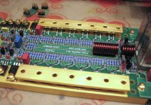
PCB for the +/-80V regulator is done.........Now onto the input/VAS PCB.........
An externally hosted image should be here but it was not working when we last tested it.
Ta-da!
G.Kleinschmidt said:Huh?
Another 256 Re's for the AB stage, makes a total of 496 you''ll be soldering.
I fail to see the advantage with such numbers involed, unless you'll spend a month in the slammer for masacring a kangaroo family.
What's the cost of a 1 watt metalfilmer in Bauxtralia ?
G.Kleinschmidt said:
Hi, I am not sure about short circuit protection circuit, together with Hawksford's circuit it will saturate protection transistors when short circuit happens IMO. This is contrary to typical output stages, where active protection has proper Vce.
jacco vermeulen said:
Another 256 Re's for the AB stage, makes a total of 496 you''ll be soldering.
I fail to see the advantage with such numbers involed, unless you'll spend a month in the slammer for masacring a kangaroo family.
What's the cost of a 1 watt metalfilmer in Bauxtralia ?
I already metioned the advantage in a previous post. Perhaps you missed it.
darkfenriz said:
Hi, I am not sure about short circuit protection circuit, together with Hawksford's circuit it will saturate protection transistors when short circuit happens IMO. This is contrary to typical output stages, where active protection has proper Vce.
No! The protection transistors (as well as the EC circuit transistors) do not saturate on current limit. At the current limit of 64A, the 'error voltage' between the output and the end of the 750 ohm resistor clamped by the protection transistors will be in excess of 2V. The protection transistors clamp this voltage to maintain a constant load current - just like in a normal output stage.
Since the protection transistors clamp the 'error voltage', the EC circuit is inhibited also.
Cheers,
Glen
Upupa Epops said:Glen, look at " two pins " transistors, maybe something burn in your head... 😎
Yes, I know. The brass is at rail potential, connected to the drain/collector tabs......
How I see it ( I may be wrong and if so please don't be angry):
These 2V is all you can freely clamp, after this 2V clamped saturation must happen. By altering the output voltage by 2V you won't protect output from short at high amplitude.
regards
Adam
These 2V is all you can freely clamp, after this 2V clamped saturation must happen. By altering the output voltage by 2V you won't protect output from short at high amplitude.
regards
Adam
G.Kleinschmidt said:missed it.
Think so, i'd expect something like Fu-Fu low inductance 5W Re's in a 2 x 56 output device design (MPC71/MPC722)
Safes 75-80% of the soldering and 20% cheaper than 5 MFs in parallel, unless MF are cheaper than skippy droppings in Oz.
Is it the inductance ?
darkfenriz said:How I see it ( I may be wrong and if so please don't be angry):
These 2V is all you can freely clamp, after this 2V clamped saturation must happen. By altering the output voltage by 2V you won't protect output from short at high amplitude.
regards
Adam
I'm not going to get angry 🙂
Saturation doesn't happen because there is always >1V Vce across the protection transistor when it is limiting the output current.
The action is self regulating.
When the output is conducting a load current of 64A, there will be an 'error voltage' in excess of 2V present between the end of R1 which is clamped by the protection transistors and the output (to which the emitters of the protection transistors are connected).
The 'error voltage' is mostly defined by the voltage drop developed across the emitter ballast resistors for the output transistors.
The protection transistors begin to conduct at a load current in excess of 64A, thus preventing the 'error voltage' from going any higher. If the error voltage cannot rise, neither can the output current.
Cheers,
Glen
G.Kleinschmidt said:
How are you going to achieve a quiet +/-7V 64A supply? How are you going to regulate it against mains line fluctuations? The classic brute force unregulated approach with huge filter capacitors may easily produce 5V today and 9V tomorrow... This calls for a SMPS too...
Eva said:
How are you going to achieve a quiet +/-7V 64A supply? How are you going to regulate it against mains line fluctuations? The classic brute force unregulated approach with huge filter capacitors may easily produce 5V today and 9V tomorrow... This calls for a SMPS too...
64A is the peak load current limit. The actual bias current is 16A for class A operation up to 1kW into 2ohms.
Mains fluctuations will never cause as severe a fluctuation as 5 to 9V (1.8:1) and the class A output stage is entirely immune to fluctuations of its supply rails of this magnitude anyway. +/-7V gives ample operating headroom. A SMPS here would be pointless.
Cheers,
Glen
Upupa Epops said:It is not brass, Glen, but vermeil of copper...
Sound like something from a recipe book. Like cream of mushroom................

jacco vermeulen said:
Think so, i'd expect something like Fu-Fu low inductance 5W Re's in a 2 x 56 output device design (MPC71/MPC722)
Safes 75-80% of the soldering and 20% cheaper than 5 MFs in parallel, unless MF are cheaper than skippy droppings in Oz.
Is it the inductance ?
Inductance has most to do with it. Typical wire wound resistors of less than 1 ohm such as the common 5W ceramic and vitreous enamel types are ruled out for this reason.
The resistors I’m using cost about 15 cents each bought in the quantity I need.
I see you have your reasons for doing so, but there are decent non-inductive power resistors available. Mills resistors come to mind (2W, 5W, and 12W are commonly available). Not cheap, but I guess if you don't mind soldering a whole lot of resistors your solution is fine.
- Status
- Not open for further replies.
- Home
- Amplifiers
- Solid State
- My 1024W RMS CLASS A+ amplifier.