Eva said:Are you making prototypes and testing and improving every section, or are you expecting such a complex thing to work in the first attempt? Are you going to lay out PCBs? What if you discover that you have to do some changes after the PCB is assembled?
BTW: What schematics drawing softare are you using?
I've been designing and building circuits like these (and more complicated) for years. The circuits are not functionally complicated in the least - don't be fooled by the number of components. I know that they will work becuse I've done it 10+ times already. If I do make a stuff up on one of the boards, they I'll just throw away $20 worth of PCB material and etch a new modified one.
I use Protel 99SE, with my own custom creation symbol set. I'm not telling how I make the *.GIF files though.
Nelson Pass said:
Got enough emitter resistors there, Glen?
😎
Yep.
This way I can use cheap non-inductive resistors to make a single low resistance, and spread the dissiaption over a larger area. 5mm spacing between each resistor - this gives me a 50mm spacing between each of the six power transistors. I have 6 pairs in the class A core, giving a PCD of 300mm. This will take good advantage of a large chunk of the heatsink area.
Oh, and did I mention that the entire 1500mm X 220mm flat inside surface of my heatsinks are going to be clad in a thick, thermally bonded sheet of copper?
Cheers,
Glen
wow, that array of emitter resistors looks like an ammunition belt!
I don't understand why everyone is bent on forcing Glen to use a Class D stage for the rails instead of AB...it's his amp, and he chose to use an AB stage for his own reasons where he felt a switching amplifier wouldn't cut it for his purposes. If it really gets your shorts in a knot that he didn't use a Class D amplifier 'for the wrong reasons', how about building your own with a Class D stage instead of throwing a fit about something that obviously is impractical to implement at this stage of the amplifier's construction? Sometimes it seems like an engineering degree is treated as a license to be pompous around here. Original and creative concepts have a way of being shot down before they take flight.
Anyway, good luck with the amp, it surely will be a stunner when complete. Now all you need is to add a few glowing valves for decoration... 😀
G.Kleinschmidt said:
Oh, and did I mention that the entire 1500mm X 220mm flat inside surface of my heatsinks are going to be clad in a thick, thermally bonded sheet of copper?
Hi Glen,
The comment above piqued my interest. How will you thermally bond copper to aluminum? What will you use?
BTW, looks good so far.🙂
If I may make a general statement here:
There seems to be a fair degree of negitivity towards Glen's
design.
It's worth considering that even with -0- global feedback, just
the OP error correction and OP class A bias should enable very
low distortion. My educated guess is that with the EC trimmed,
around 0.00x% would be acheivable up to very high powers sans
global feedback.
Personally I would have run two FB loops, IP stage and unity
gain OP stage, no glob FB. However I'm quite sure the way Glen
has done it is absolutely feasable with some degree of
compensation tweaking.
Let the man pursue his idea, let's help him if we can and let us
await the results. I am sure there will be something to be
learned by all here.
cheers
Terry
Terry Demol said:There seems to be a fair degree of negitivity towards Glen's
design.
No negativity from me. Sano et al's design is "one I wish I did",
and disagree with the carping about whether it qualifies as Class A.
Glen is correct when he points out that any distortion on the part
of the Class AB amplifier has a negligible contribution to the
performance of the Class A stage, and with EC applied to it, we
might get to see some interesting results.
😎
Hi Guys,
I don't have a problem with the design either. I was only trying to point out an alternative that I believed would inject less noise into the audio path through the capacitance of the actual amplifier stage.
It is more the attitude.
Besides, it is his design and parts of which I feel he is doing very well. That is why I've unsubscribed to this thread a while ago.
Darn, now I have to unsubscribe again!
Hi Nelson,
The only thing that the class B tracking power supply might do is inject transients when changing polarity. The same way the Carver style amps do (after he went away from the bang - bang switching). Since I've seen this before, I was trying to warn Glen of the possibility.
-Chris
anatech said:Hi Guys,
I don't have a problem with the design either. I was only trying to point out an alternative that I believed would inject less noise into the audio path through the capacitance of the actual amplifier stage.
It is more the attitude.
Besides, it is his design and parts of which I feel he is doing very well. That is why I've unsubscribed to this thread a while ago.
Darn, now I have to unsubscribe again!
Hi Nelson,
The only thing that the class B tracking power supply might do is inject transients when changing polarity. The same way the Carver style amps do (after he went away from the bang - bang switching). Since I've seen this before, I was trying to warn Glen of the possibility.
-Chris
A few points:
A class AB amplifier will inject LESS noise than a switching amplifier. The amount of low pass filtering, which would be required to adequately reduce the switching ripple (even for switching frequencies well above 40KHz) would produce a driver for the class A rails which wouldn’t have buckleys chance of keeping up with the slew rate of the class A amplifier I have designed.
With regards to crossover feed through, I don’t know the circuit details of the Carver amp you are referring to, but you did say that the crossover “pip” of the class B stage was visible on the class A tracking rails using an oscilloscope. If this was the case, then the Carver amp used a class B stage/ amplifier with VERY high distortion.
This is not the case in the Technics A+ topology – which uses a very low distortion Class B amplifier. You would never be able to see its crossover blip with an oscilloscope monitoring it's output.
Cheers,
Glen
bikehorn said:wow, that array of emitter resistors looks like an ammunition belt!
I don't understand why everyone is bent on forcing Glen to use a Class D stage for the rails instead of AB...it's his amp, and he chose to use an AB stage for his own reasons where he felt a switching amplifier wouldn't cut it for his purposes. If it really gets your shorts in a knot that he didn't use a Class D amplifier 'for the wrong reasons', how about building your own with a Class D stage instead of throwing a fit about something that obviously is impractical to implement at this stage of the amplifier's construction? Sometimes it seems like an engineering degree is treated as a license to be pompous around here. Original and creative concepts have a way of being shot down before they take flight.
Anyway, good luck with the amp, it surely will be a stunner when complete. Now all you need is to add a few glowing valves for decoration... 😀
Terry Demol said:If I may make a general statement here:
There seems to be a fair degree of negitivity towards Glen's
design.
It's worth considering that even with -0- global feedback, just
the OP error correction and OP class A bias should enable very
low distortion. My educated guess is that with the EC trimmed,
around 0.00x% would be acheivable up to very high powers sans
global feedback.
Personally I would have run two FB loops, IP stage and unity
gain OP stage, no glob FB. However I'm quite sure the way Glen
has done it is absolutely feasable with some degree of
compensation tweaking.
Let the man pursue his idea, let's help him if we can and let us
await the results. I am sure there will be something to be
learned by all here.
cheers
Terry
Nelson Pass said:
No negativity from me. Sano et al's design is "one I wish I did",
and disagree with the carping about whether it qualifies as Class A.
Glen is correct when he points out that any distortion on the part
of the Class AB amplifier has a negligible contribution to the
performance of the Class A stage, and with EC applied to it, we
might get to see some interesting results.
😎
Thanks!
MJL21193 said:
Hi Glen,
The comment above piqued my interest. How will you thermally bond copper to aluminum? What will you use?
BTW, looks good so far.🙂
I was thinking about some of that fancy sticky sided silicon inpregnated (or whatever they call it) rubber sheet stuff, but fell over when I saw the price. Looks like I'll just end up using lots of plain old gooey heatsink compound.
Cheers,
Glen
Well…
I have already expressed my opinion in another tread!
So... you have the pictures…
Pero que las hay, las hay… 😀
I have already expressed my opinion in another tread!
So... you have the pictures…
Pero que las hay, las hay… 😀
Alrighty, the Class B power output module schematic is now done (do not connect headphones here!).
http://users.picknowl.com.au/~glenk/MAIN.HTM (Input/VAS module)
http://users.picknowl.com.au/~glenk/CLASSA.HTM (Class A EC power output module)
http://users.picknowl.com.au/~glenk/80VREG.HTM (+/-80V Regulator)
http://users.picknowl.com.au/~glenk/CLASSB.HTM (1kW class B power output module)
Now onto the overload crowbar and protection circuits.......
Cheers,
Glen
TOINO said:Well…
I have already expressed my opinion in another tread!
So... you have the pictures…
Pero que las hay, las hay… 😀
That's a class G amplifier. I've designed one of those as a series modulator for a class E AM RF power amplifier, which I have yet to build. I can post the schematic if you want.
Cheers,
Glen
G.Kleinschmidt said:
I was thinking about some of that fancy sticky sided silicon inpregnated (or whatever they call it) rubber sheet stuff, but fell over when I saw the price. Looks like I'll just end up using lots of plain old gooey heatsink compound.
Hi Glen,
A completely solid attachment of the two metals might result in bending with temperature change - similar to a bi-metal bar in a thermistat.
Something to consider.
I'm interested in your design, but would like to try it on a smaller scale. 1Kw/channel is a tad high for my purposes.🙂
Keep up the good work.
G.Kleinschmidt said:
That's a class G amplifier. I've designed one of those as a series modulator for a class E AM RF power amplifier, which I have yet to build. I can post the schematic if you want.
Cheers,
Glen
Hi Glen
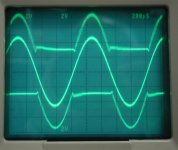
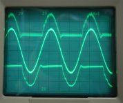
It seems a class-G, but it is not... or maybe it is.
I mean: it is a class-G but Switched instead of linear.
Now I realize that it is a completely new kind of amplifier! 😱
If you look closer, you could see the Hf residual on the 5KHz picture😉
TOINO said:It seems a class-G, but it is not... or maybe it is.
I mean: it is a class-G but Switched instead of linear.
For what it's worth, I built a Class G with a Class A main output
stage amplifier in the mid-70's. It worked as you would imagine,
but the glitch when the "G" kicked in was larger than the notch
you would get on a Class AB. It was not worth the effort.
😎
Hi 😀G.Kleinschmidt said:Alrighty, the Class B power output module schematic is now done (do not connect headphones here!).
http://users.picknowl.com.au/~glenk/MAIN.HTM (Input/VAS module)
http://users.picknowl.com.au/~glenk/CLASSA.HTM (Class A EC power output module)
http://users.picknowl.com.au/~glenk/80VREG.HTM (+/-80V Regulator)
http://users.picknowl.com.au/~glenk/CLASSB.HTM (1kW class B power output module)
Now onto the overload crowbar and protection circuits.......
Cheers,
Glen
It excuses my ignorance but it would be pleasant to also see a block diagram of the whole amplifier.
Thanks. 😀
Nelson Pass said:
..the glitch when the "G" kicked in was larger than the notch
you would get on a Class AB..
Seems that is the price we must pay for efficiency nowadays…
Wish I have meeting you here at mid-90's because I have made precisely the same.
Nastiest with Hawksford.

- Status
- Not open for further replies.
- Home
- Amplifiers
- Solid State
- My 1024W RMS CLASS A+ amplifier.